Do you have a question about the ISA CBA2000 and is the answer not in the manual?
Details EMC standards, emission, and immunity tests.
Covers safety standards for low voltage equipment.
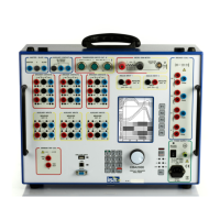
Overview of the CBA2000 as a two-in-one test set.
Off-line testing of MV/HV circuit breakers and operation times.
Measuring contact resistance and performing dynamic tests.
Highlights display, memory, USB transfer, inputs, triggers, and sequences.
Details of the electronic driver for breaker coils.
Specifications for main contact sensing circuits and pre-insertion resistor test.
Features of auxiliary inputs for dry/wet contacts and relay output.
Timing measurement ranges, resolutions, and accuracies.
Characteristics of ten programmable analog inputs for various measurements.
Options for initiating time measurements (coil current, auxiliary input, etc.).
User-programmable test sequences with adjustable delays.
Measuring static resistance with selectable test currents.
Recording contact resistance profile during CB closing.
Local control via keypad, selectors, display and pushbuttons.
Data transfer via RS232 and USB, and saving to USB memory.
Features of the TDMS software for test analysis and management.
Navigation and operation of the instrument's menu system.
Mains supply, battery, housing, dimensions, weight, and included items.
Option for performing resistance measurements.
Option to drive four coils instead of two.
Expands contact sensing and digital event inputs.
Option for an external thermal printer for test results.
Option for a built-in thermal printer.
Option to test trip coil behavior at reduced voltage.
Standard set of cables for connecting the instrument.
Option for longer connection cables for main/auxiliary contacts.
Protective case for safe transportation.
Soft bag for protecting the instrument from dust/scratches.
External module for testing with both CB ends grounded.
Analog and digital transducers for position measurement.
For measuring DC current of motors and auxiliary supply.
Clamp for performing first trip test on three phases.
Transducer for monitoring SF6 pressure variation.
Describes fuse on the mains supply for protection.
Diagnostic sequence checks microprocessors on startup.
Alarm messages for selected current range exceeded or over-temperature.
Warning message if trigger criteria not met within max test time.
5V transducer supply protected against short circuit and voltage contact.
All inputs and outputs are isolated between them.
Settings for triggering test measurements.
Configuration for various test types (Open, Close, etc.).
Settings for test recording duration and frequency.
Configuration for breaker contacts and auxiliary inputs.
Settings for analog inputs, coil ranges, and transducers.
Settings for static and dynamic resistance measurements.
Options for saving, loading, viewing, and deleting results.
Settings for date, time, display, and buzzer.
Options for saving, loading, and restoring setup configurations.
Header information for tests.
Options related to test diagrams and function keys.
| Brand | ISA |
|---|---|
| Model | CBA2000 |
| Category | Measuring Instruments |
| Language | English |