Do you have a question about the Iskra MT440 and is the answer not in the manual?
Introduction to the chapter, emphasizing careful reading before starting work with the transducer.
Explains the booklet's content for installation and use of MT440 by qualified persons.
Provides information for safe installation and handling to ensure correct use and continuous operation.
Lists critical checks required before switching on the device.
Explains used symbols and contents of consignment.
Explains the meaning of symbols and tables used within the manual for clarity.
Provides definitions for technical terms and abbreviations used in the manual.
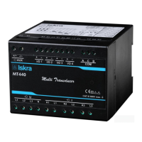
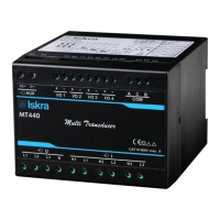
Describes the MT440's purpose, measurement capabilities, and built-in microcontroller functions.
Details the instrument's application for monitoring three-phase electrical power systems.
Instructions for connecting the transducer, emphasizing safe handling of currents and voltages.
Details the DIN rail mounting procedure for the MT440 measuring transducer.
Explains connecting voltage and current inputs to low-voltage or medium/high-voltage networks.
Describes connecting electromechanical, solid-state, and analog output modules.
Details serial (RS232/RS485) and USB communication port connections and setup.
Explains connecting the universal AC/DC auxiliary power supply to the designated terminals.
Explains how instrument settings can be modified remotely via communication or software.
Information on MiQen software for monitoring, settings, real-time measurements, and upgrading.
Steps for modifying instrument settings using MiQen software, including loading parameters.
Covers connection, communication, display, and security settings for the transducer.
Setting parameters related to input/output connections, voltage, and current ratios.
Configuration of serial (COM1) and USB communication parameters for data transfer.
Explains password settings and security levels for accessing and protecting parameters.
Settings related to active tariff, common energy exponent, and counter divider for energy measurement.
Configuration of analog, fast analog, solid-state, and relay output modules.
Setting up to 16 alarms in two groups for exceeded measured quantities.
Procedures for resetting energy counters, MD values, and alarm statuses.
Explains that device operation will be detailed in subsequent chapters.
Lists measurements supported by the instrument, varying with connection settings.
Describes different electric connection types and their markings for measurement configuration.
Defines sample factor (My) and average interval (Mp) essential for measurement accuracy.
Details how measurements are captured, calculated, and displayed on the device.
Explains how voltage, current, power, PF, frequency, energy, MD, and THD are presented.
Lists safety, EMC, and measurement standards applied to the transducer.
Presents total accuracy for measurements and analog output as per IEC/EN 60 688.
Details specifications for voltage and current inputs, frequency, and power supply.
Specifies permitted conductor cross-sections for terminal connections.
Technical specifications for electromechanical, solid-state, and analog output modules.
Technical data for RS232, RS485, and USB communication interfaces.
Details response time for communication and status LED indicators.
Information on protection class, pollution degree, installation category, and EMC compliance.
Mechanical specifications including dimensions, mounting, and enclosure materials.
Specifies operating and storage temperatures, and humidity limits.
Provides a diagram with the physical dimensions and mounting details of the transducer.
Explains Modbus protocol, versions, and register tables for measurements and settings.
Lists symbols and their definitions used in various electrical calculations.
Provides detailed mathematical equations for voltage, current, power, THD, and energy.
| Brand | Iskra |
|---|---|
| Model | MT440 |
| Category | Transducer |
| Language | English |