Measurements
User’sManual 31
With this method, reactive power (energy) represents only true reactive component of apparent
power (energy).
All measurements are seen via communication. For more detailed information about calculation
see chapter
Equations on page 53.
Power factor and power angle
Power factor is calculated as quotient of active and apparent power for each phase separately
(cosϕ
1
, cosϕ
2
, cosϕ
3
) and total power angle (cosϕ
t
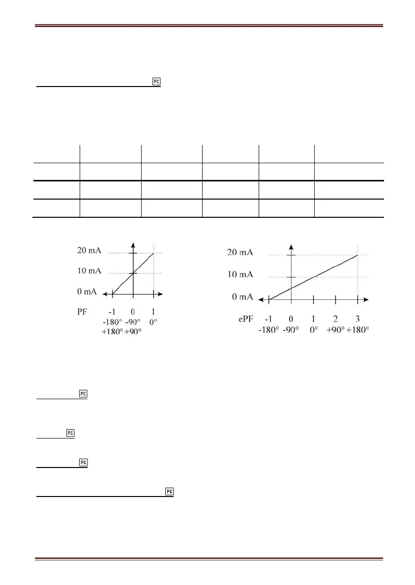
). For correct display of PF via analog output
and application of the alarm, ePF (extended power factor) is applied. It illustrates power factor
with one value as described in the table below. For a display on the remote display both of them
have equal display function: between −1 and −1 with the icon for inductive or capacitive load.
Load C
→
L
Angle [°] −180 −90 0 +90 +180 (179.99)
PF −1 0 1 0 −1
ePF −1 0 1 2 3
Example of analog output for PF and ePF:
Power angle represents angle between first voltage harmonic and first current harmonic for each
individual phase. Total power angle is calculated from total active and reactive power (see
equation for Total power angle, chapter
Equations on page 53). A positive sign shows inductive
load, and a negative sign shows capacitive load.
Frequency
Network frequency is calculated from time periods of measured voltage. Frequency is an average
of number of periods set in General settings/average interval.
Energy
Energy of each of four energy counters is available.
MD values
Measurements of MD values.
THD − Total harmonic distortion
THD is calculated for phase currents, phase and phase−to−phase voltages and is expressed as
percent of high harmonic components regarding RMS value or relative to first harmonic.
Instrument uses measuring technique of true RMS values that assures exact measurements with
the presence of high harmonics up to 31st harmonic.