Basicdescriptionandoperationofmeasuringtransducer
User’sManual 7
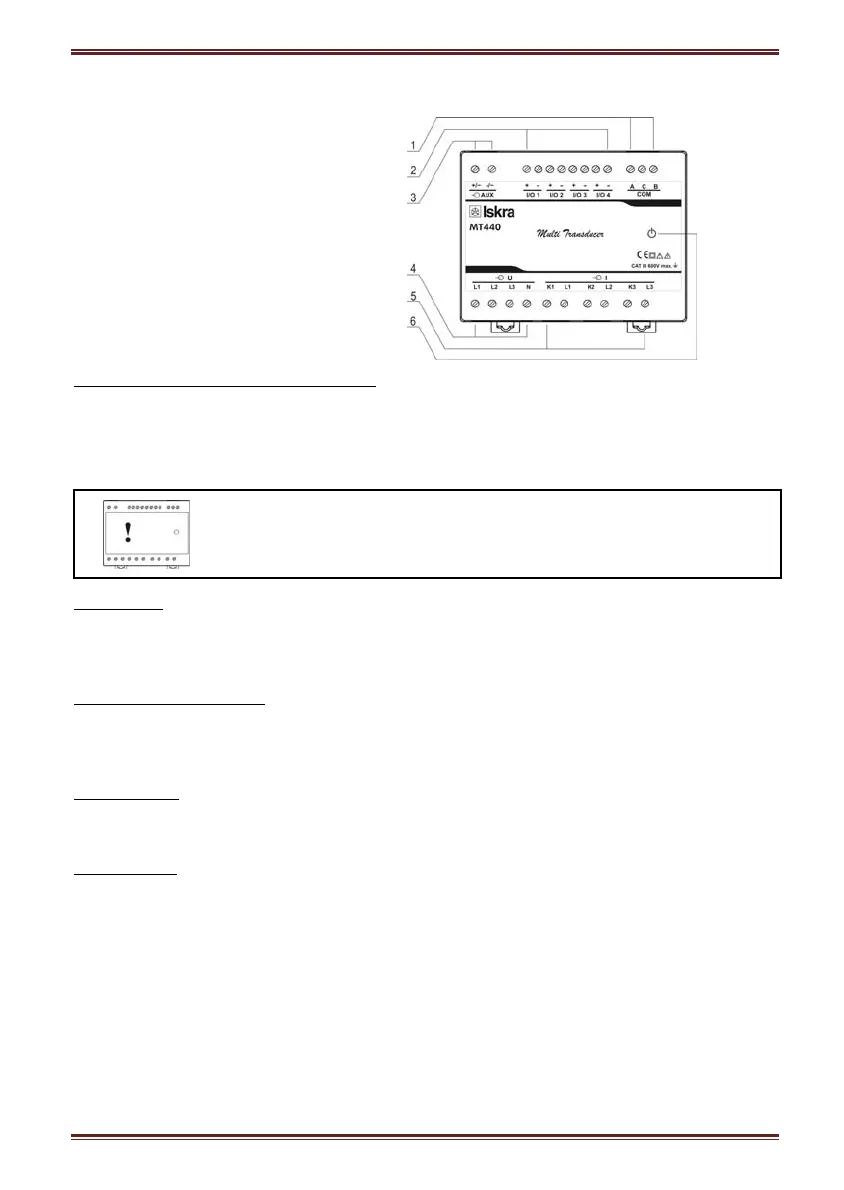
Appearance
Measuring transducer can differ from yours depending on the type and functionality.
1 – Communication ports
2 – I/O modules
3 – Auxiliary supply
4 – Voltage inputs
5 – Current inputs
6 – Power ON LED
Communication ports and LED indicators
Serial communication can be connected by using screw-in connector (RS232 or RS485). USB
can be connected through USB-mini type connector at the bottom of transducer.
LED indicator is intended for POWER ON signaling (red LED).
Warning!
USB communication port is provided with only BASIC insulation and can
ONLY be used unconnected to aux. supply AND power inputs!
I/O modules
Four I/O module slots are intended for various I/O modules, which should be chosen at placing
the order. Analog outputs, fast analog outputs, relay outputs (alarm, pulse, general-purpose
digital outputs) and solid-state relay outputs (alarm, pulse, general-purpose digital outputs).
Universal auxiliary supply
Auxiliary supply is connected by two screw-in connectors. For safety purposes it is important
that all wires are firmly fastened. Auxiliary supply is wide range (24 V
DC
– 300 V
DC
; 40 V
AC
–
276 V
AC
).
Voltage inputs
Each voltage input is connected to measuring circuit through input resistor chain (3.3 MΩ per
phase). Maximum value of input voltage is 600 V
L-N
(1000 V
L-L
).
Current inputs
Each current input is connected to measuring circuit through current transformer (0.01
Ω per
phase). Maximum allowed thermal value of input current is 15A (cont.).