SMOKEDOME
PARTS
REAR
FRONT
END
END
FRONT REAR
17
Assembly Instructions - (cont.)
Step 7: With the damper beams assembled and mortared
together, set the cast iron throat damper on top of the damper
plate and over the damper plate opening. The cast iron
damper’s operating plate should face toward the rear of the
replace. (Figure 16)
The ange at all four sides of the cast iron damper
should be supported by the damper beam’s top surface.
Before adjusting the cast iron damper to its nal
position proceed to Step 8.
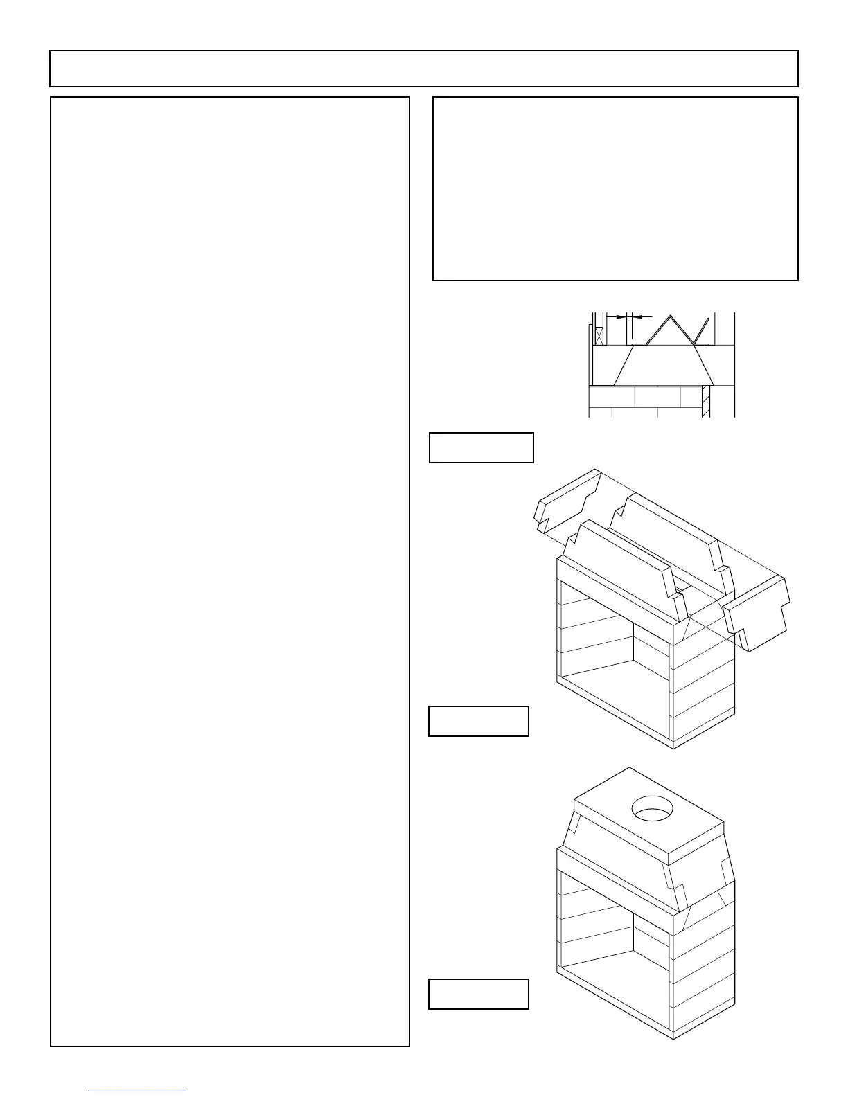
Step 8: Set the back smoke dome component across the
damper beam in a bed of mortar and ush with the back face
of the back damper plate lintel. (Figure 17)
Set the front smoke dome component in mortar
across the damper plate and 2 -1/4 inches back from the front
of the front damper plate lintel. This placement should create
a space of 17 inches between the front and back smoke dome
components.
Position the cast iron damper so that its front ange
is approximately one inch (1”) away from the inside face of
the front smoke dome component.
(Figure 16)
Run a thin bead of mortar around the four sides of
the cast iron damper ange to avoid movement of the damper
as it gets opened and closed.
Step 9: Position the smoke dome’s sloping sidewalls at each
end of the smoke dome components. (Figure 17)
The sloping sidewalls t in between the front and
rear smoke dome components and also t into the haunches
at the ends of the front and rear smoke dome components.
Mortar all contact surfaces thoroughly.
Note: The smoke dome sloping sidewalls have a beveled
bottom edge so that they will sit tight onto the at top of the
damper beam.
Step 10: Make sure that all component contact surfaces have
been properly sealed with approved mortar.
Check smoke dome front and back walls to see
that they are plumb, level and in alignment with mating
components.
Check alignment of the smoke dome sloping
sidewall components to see that they are fully seated.
Step 11: Set the smoke dome top plate into position on top of
the smoke dome wall assembly. (Figure 18)
One side of the smoke dome top plate shows a
thickened center. This side is the bottom face of the top plate.
The fourteen inch (14”) diameter ue hole in the top
plate is centered in the smoke dome from side to side but is
offset from front to back.
FIGURE 17
FIGURE 18
FIGURE 16
Make sure that the top plate is set so that the ue hole is
closer to the back wall of the smoke dome assembly.
Be sure to set the smoke dome top plate ush with
the front, back and sides of the smoke dome assembly. All
contact surfaces must be properly sealed with the approved
mortar.
Note: The completed smoke dome assembly should present
a stable and level surface for setting the ue components.
(Figure 18)

 Loading...

