62
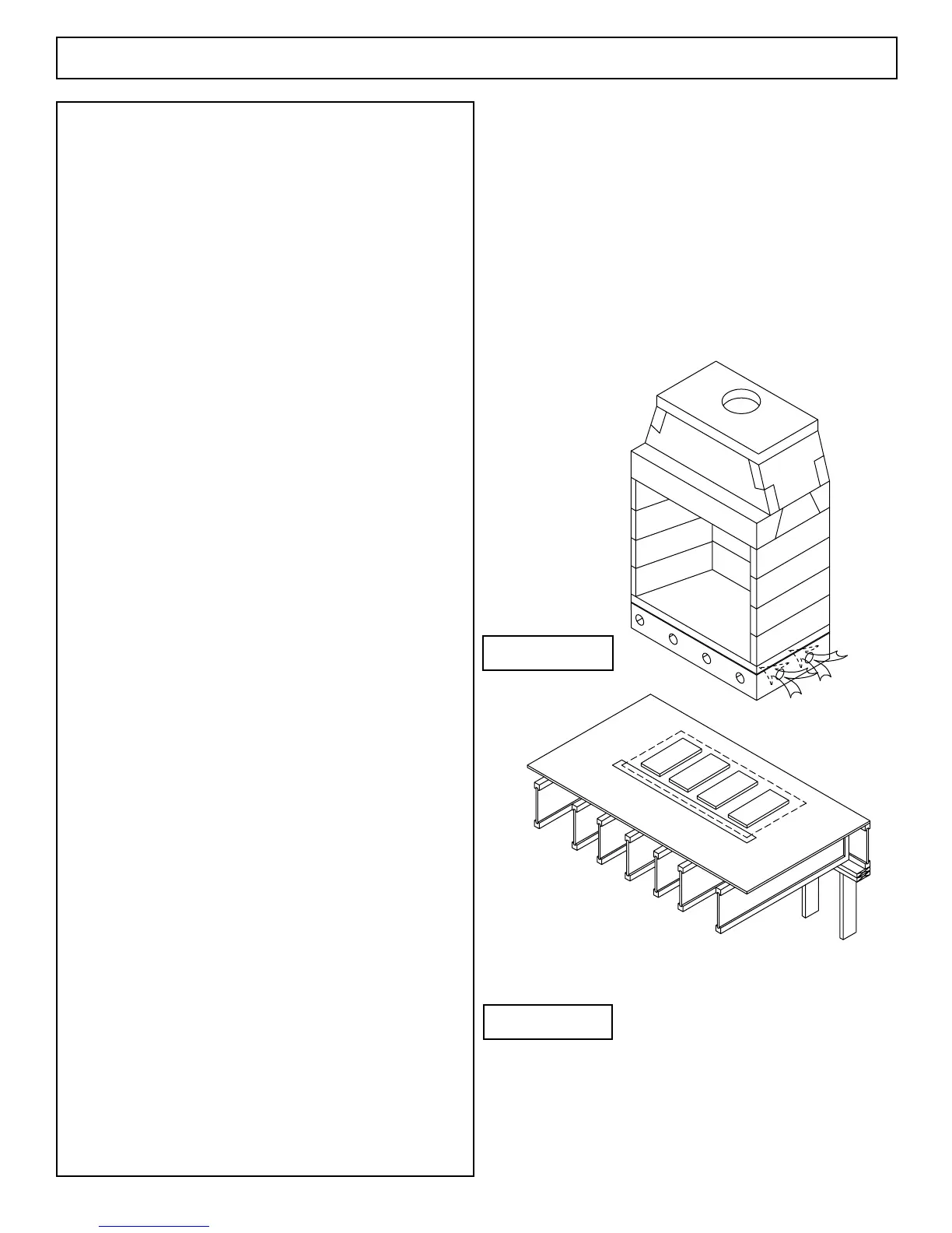
Floor framing for a Fire-Lite installation will need to
be designed and built to accept substantial dead loads spread
over a relatively small oor area.
The following weights and sizes can be used to
calculate Fire-Lite loading. Consult with local structural
engineer for proper sizing of structural oor frame members for
specic installations.
Load Calculations:
Total dead load amounts include (but are not necessarily
limited to) the following items and their corresponding weight
estimates listed below:
1. Fire-Lite unit model weights:
a. Model 36 FP: 1360 lbs.
b. Model 42 FP: 1450 lbs.
c. Model 48 FP: 1600 lbs.
2. Damper, re brick and mortar: 450 lbs.
3. Raised platform: 40 lbs.
4. Fireplace nished facing: approx. 200 lbs.
5. Weight of metal ue: negligible
By adding the weight of the appropriate Fire-Lite
Model listed in #1 above to the allowance given for each item in
2 through 5, above, the total weight of the Fire-Lite Series can
be estimated.
Total approximate Fire-Lite Series weight estimates for each
Model:
Model 36 FP @ 1360 lbs. + items 2 thru 5 @ 690 = 2050 lbs.
Model 42 FP @ 1450 lbs + items 2 thru 5 @ 690 = 2140 lbs.
Model 48 FP @ 1600 lbs + items 2 thru 5 @ 690 = 2290 lbs.
The oor area for each model is as follows:
Model 36 FP @ 43” x 25.25” = 7.54 sq.ft.
Model 42 FP @ 48.5” x 25.25”= 8.50 sq.ft.
Model 48 FP @ 53” x 25.25” = 9.30 sq.ft.
Notes:
These dead load totals are in addition to the live load
and other dead load requirements for the specic site’s proposed
oor.
The load estimates given above for items are estimates
only and may not accurately dene total loads related to the
completed replace due to material choices that are at owner
option.
Consult your local structural engineer for proper oor
system design, sizing and specications.
Isokern is not responsible for structural oor support
details for the Fire-Lite replace. Unless otherwise noted all
oor framing drawings in this manual are merely illustrations to
indicate the presence of an underlying oor system.
Fire-Lite Application - Combustible Floor System
FIGURE 127
FIGURE 128

 Loading...

