EasyManua.ls Logo

Isolite E3-MAC Series User Manual

Isolite E3-MAC Series
40 pages
To Next Page IconTo Next Page
Page #1 background imageLoading...
Page #1 background image
1KW -12.5KW
SINGLE PHASE
MODELS
1KW MODEL
SHOWN
ISOLITE – THE EMERGENCY LIGHTING EXPERTS
31 Waterloo Avenue Berwyn, PA 19312 WWW.ISOLITE.COM
IMPORTANT SAFEGUARDS
When using electrical equipment, basic safety precautions should always be followed
including the following:
READ AND FOLLOW ALL SAFETY INSTRUCTIONS
A. Do not use outdoors
B. Do not mount near gas or electric heaters.
C. Use caution when servicing batteries. Battery acid can cause burns to skin and
eyes. If acid is spilled on skin or in eyes, flush acid with fresh water and
contact a physician immediately.
D. Equipment should be mounted in locations and at heights where it will not
readily be subjected to tampering by unauthorized personnel.
E. The use of accessory equipment not recommended by the manufacturer may
cause an unsafe condition.
F. Do not use this equipment for other than intended use.
This unit contains lethal voltages. There are no user serviceable parts inside. Only
authorized service personnel are to be used for service.
SAVE THESE INSTRUCTIONS
The installation and use of this product must comply with all national, state, municipal
or local codes that apply. Please read this manual thoroughly before installing and
operating the E3-MAC Series central inverter system. For assistance please call ISOLITE
technical support at 800-967-5573 and speak to a technician during normal business
hours (EST).
Installation / Operation Manual
Emergency Lighting Central Inverter System
E3-MAC Series by
Question and Answer IconNeed help?

Do you have a question about the Isolite E3-MAC Series and is the answer not in the manual?

Isolite E3-MAC Series Specifications

General IconGeneral
BrandIsolite
ModelE3-MAC Series
CategoryInverter
LanguageEnglish

Summary

IMPORTANT SAFEGUARDS

Safety Instructions

Read and follow all safety instructions for proper operation and use.

Introduction

Mechanical Design Features

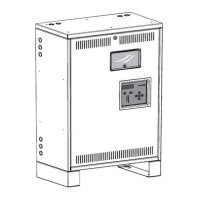
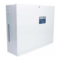
Details the design of the inverter for ease of installation and durability.

Electrical Design Features

Explains the PWM technology, IGBT/MOSFET usage, and sine wave output.

Receiving and Storage

Inspection Upon Arrival

Procedure for inspecting the inverter and batteries for shipping damage.

Storage Guidelines

Recommendations for optimal storage temperature and time to prevent damage.

Installation

Location Requirements

Guidelines for selecting a suitable permanent mounting location for the unit.

Operating Environment

Specifies the optimal temperature range for battery life and system performance.

Ventilation and Clearance

Requirements for air circulation and physical space around the inverter cabinet.

Floor Preparation

Instructions for ensuring a level and secure mounting surface for the cabinet.

Cabinet Configurations

Overview of available cabinet sizes and knockout locations for wiring.

AC Connections

Removing AC Breaker Cover

Steps for safely accessing the breaker panel by removing the cover.

Installing Input Wires

Procedure for connecting the incoming AC power wires to the system.

Installing Output Wires

Guidance on connecting load wires to output terminal blocks or breakers.

Special Options

Details on custom configurations like bypass switches and trip alarms.

Battery and DC Connections

Battery Inspection

Checks for physical damage and electrolyte leaks before installation.

Battery Installation/Removal

Step-by-step guide for installing and removing batteries.

DC Voltage of System

Information on required string voltage based on system size and battery configuration.

Battery Hardware

Details on battery hardware, torque specifications, and pre-installation checks.

Battery Pre-Checks

Recommended measurements to determine battery health before system startup.

Startup and Shutdown Procedures

Startup Procedure

Steps for powering up the unit, verifying connections, and entering charge mode.

Shutdown Procedure

Instructions for safely turning off the system and considerations for long-term storage.

System Operation

Startup Mode

Process the unit follows after initial power-up, including self-tests and diagnostics.

Battery Charging Mode

The system's primary mode, maintaining float charge on batteries.

Inverter Mode

Operation where the inverter supplies power and batteries discharge.

Output Types

Explanation of Normally-On, Normally-Off, and Switched output functionalities.

Specifications

Ordering Information

Warranty

Technical Service and Support

Information on contacting technical support and service center contact details.

Return Material Authorization (RMA)

Procedure for returning defective parts and obtaining an RMA number.

Man Machine Interface (MMI)

MMI Introduction

Overview of the MMI components: keypad, display, LEDs, and buttons.

MMI Controls and Features

Details on System Test, Alarm Silence, Keypad, Display, SD/USB slots, and Main Menu.

Menu Navigation and Logs

Description of Meter Menu, Alarm Menu, and Event Log functionalities.

Log Management and Testing

Details on Test Log, Alarm Log, User Menu, and system test requirements.

Configurable Alarms and Time Delay

Explanation of Low/High VAC, Battery, Temperature alarms, and Time Delay feature.

Advanced Features and Logging

Details on Load Reduction, Relays, Backup Logs, Contact Name/Phone.

Maintenance and Service

Routine Maintenance Tasks

Periodic cleaning and system self-tests including monthly and yearly test procedures.

Battery Maintenance

Recommendations for visual inspection of batteries every six months.

Battery Replacement Procedure

Steps and warnings for safely replacing batteries in the unit.

Web Interface

User Setup and Control Panel

Guide for setting up a user account and navigating the web control panel.

System Configuration and Alarms

User adjustable settings for alarms, date/time, and viewing system alarms.

Charts and Graphs Overview

Introduction to real-time data visualization capabilities.

Data Visualization Details

Specifics on graphing Temperature, Output VA, Battery Voltage, and discharge data.

System Log Descriptions

Explanation of Test, Event, Alarm, and Discharge log contents.

Related product manuals