EasyManua.ls Logo

Isolite E3MINI Series - User Manual

Isolite E3MINI Series
32 pages
Print Icon
To Next Page IconTo Next Page
Loading...
IMPORTANT SAFEGUARDS
When using electrical equipment, basic safety precautions should always be followed
including the following:
READ AND FOLLOW ALL SAFETY INSTRUCTIONS
A. Do not use outdoors
B. Do not mount near gas or electric heaters.
C. Use caution when servicing batteries. Battery acid can cause burns to skin and
eyes. If acid is spilled on skin or in eyes, flush acid with fresh water and
contact a physician immediately.
D. Equipment should be mounted in locations and at heights where it will not
readily be subjected to tampering by unauthorized personnel.
E. The use of accessory equipment not recommended by the manufacturer may
cause an unsafe condition.
F. Do not use this equipment for other than intended use.
This unit contains lethal voltages. There are no user serviceable parts inside. Only
authorized service personnel are to be used for service.
SAVE THESE INSTRUCTIONS
The installation and use of this product must comply with all national, state, municipal
or local codes that apply. Please read this manual thoroughly before installing and
operating the E3MINI Series central inverter system. For assistance please call ISOLITE
technical support at 800-967-5573 and speak to a technician during normal business
hours (EST).
E3MINI Series by
ISOLITE – THE EMERGENCY LIGHTING EXPERTS
31 Waterloo Avenue Berwyn, PA 19312 WWW.ISOLITE.COM
Installation / Operation Manual
Emergency Lighting Central Inverter System
Question and Answer IconNeed help?

Do you have a question about the Isolite E3MINI Series and is the answer not in the manual?

Summary

IMPORTANT SAFEGUARDS

READ AND FOLLOW ALL SAFETY INSTRUCTIONS

Lists essential safety precautions for using electrical equipment.

INTRODUCTION TO E3 MINI SERIES

Mechanical Design Features

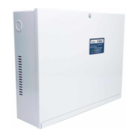
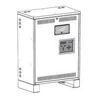
Details the physical construction and installation aspects of the unit.

Electrical Design Features

Explains the advanced electrical technology and output capabilities.

RECEIVING AND STORAGE GUIDELINES

Inspection Upon Arrival

Procedures for inspecting the inverter and batteries for shipping damage.

Proper Storage Procedures

Guidelines for storing the system to ensure battery longevity.

INSTALLATION REQUIREMENTS

Location Selection Criteria

Recommendations for choosing an appropriate installation site.

Operating Environment Specifications

Defines the ideal environmental conditions for unit performance.

Ventilation and Airflow Needs

Requirements for proper airflow and cooling to prevent overheating.

Mounting Guidelines and Hardware

Provides instructions and considerations for securely mounting the unit.

AC INPUT CONNECTIONS

Installing Input Power Wires

Step-by-step guide for connecting the incoming AC power supply.

Installing Output Wires

Instructions for connecting the unit's output wires to lighting loads.

AC Input;Output Terminal Diagram

Visual guide showing AC input and output terminal connections.

BATTERY AND DC CONNECTIONS

Battery Inspection Before Installation

Procedures for checking the condition of batteries prior to installation.

Battery Installation Procedure

Steps for physically installing the batteries into the inverter system.

Battery Wiring Diagrams

Illustrates the correct wiring for batteries in 125W and 250W models.

STARTUP AND SHUTDOWN PROCEDURES

System Startup Process

Detailed steps for powering on and initializing the system.

System Shutdown Process

Procedures for safely powering down the unit.

SYSTEM SPECIFICATIONS

Maximum Load and Power Ratings

Details maximum connected load and rated power for the system.

USER INTERFACE AND STATUS INDICATORS

LED Indicators for System Status

Explains the meaning of LED1 and LED2 for charging and inverter modes.

Alarm Condition Indicators

Describes minor and major alarms and their visual indicators.

Start-Up Fault Troubleshooting

Lists and explains faults occurring during system startup.

Charger Fault Troubleshooting

Lists and explains faults related to the battery charger operation.

Inverter Fault Troubleshooting

Lists and explains faults occurring during inverter mode operation.

SYSTEM OPERATION MODES

Startup Mode Sequence

Details the system's startup sequence and diagnostics.

Battery Charging Mode Explained

Explains the battery charging process and float voltage regulation.

Inverter Mode Operation

Describes the system's operation during power outages.

AC Output Types Overview

Overview of different output configurations like Normally-On and Switched.

WARRANTY AND TECHNICAL SUPPORT

Technical Service and Support Contact

Contact information and availability for technical assistance.

Return Material Authorization (RMA) Process

Procedure for returning defective parts for service or replacement.

MAINTENANCE AND SERVICE SCHEDULE

Routine Maintenance Procedures

Periodic cleaning and system testing for ongoing upkeep.

Battery Maintenance and Inspection

Recommended inspection schedule and care guidelines for batteries.

Battery Replacement Guide

Step-by-step instructions for safely replacing the unit's batteries.

FIRE ALARM AND DIMMING OPTION

Option Overview and Functionality

Introduction to the dimming module and its operational capabilities.

User Presets for Dimming Control

How to adjust dimming levels using the user preset controls.

Fire Alarm;Dimming Interface Wiring

Details on wiring the dimming and fire alarm interfaces.

DIMMING INTERFACE WIRING DIAGRAM

0-10 V Dimming Wiring for Lights

Diagram illustrating 0-10V dimming connections for emergency and normal lights.

CONTROL PANEL FEATURES AND ADJUSTMENTS

Switched Command and Output Operation

Explains the functionality of switched command inputs and outputs.

Dimming Adjustment (DIM ADJ) Operation

Details how to use the DIM ADJ control for dimming adjustments.

Testing the Dimmer Option Functionality

Procedures for verifying the correct operation of the dimming feature.

Charger Mode vs. Inverter Mode Operation

Comparison of system behavior in charging and inverter modes.

TYPICAL WIRING DIAGRAMS

Diagram 1: Normally-On Output Wiring

Shows the wiring configuration for the Normally-On output.

Operation: Normally-On Output Use

Explains the typical applications for the Normally-On output.

Diagram 2: Normally-Off Outputs Wiring

Shows the wiring configuration for Normally-Off outputs.

Operation: Normally-Off Outputs Use

Explains the typical applications for Normally-Off outputs.

Diagram 3: Switched Outputs Wiring

Shows the wiring configuration for Switched Outputs.

Operation: Switched Outputs Control

Explains how to control Switched Outputs using command inputs.

Diagram 4: Line Voltage Dimming Wiring

Shows the wiring configuration for line voltage dimming.

Operation: Line Voltage Dimming Use

Explains using N-ON output for dimming with bypass during inverter mode.

Diagram 5: Multiple Outputs Wiring

Illustrates wiring configurations for multiple outputs.

Operation: Multiple Outputs Application

Explains how to mix and match outputs for various applications.

Isolite E3MINI Series Specifications

General IconGeneral
BrandIsolite
ModelE3MINI Series
CategoryInverter
LanguageEnglish

Related product manuals