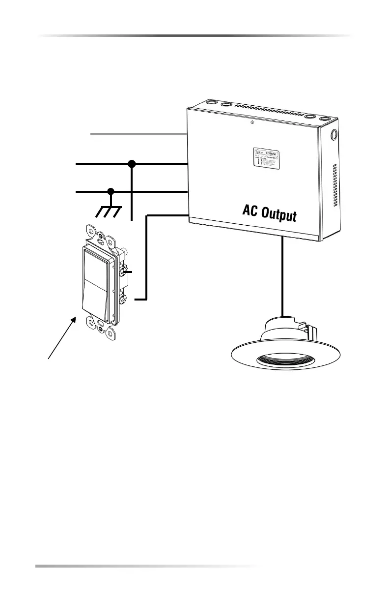
EasyManua.ls Logo

Isolite E3MINI Series - Diagram 3: Switched Outputs Wiring; Operation: Switched Outputs Control

Isolite E3MINI Series
32 pages
Print Icon
To Next Page IconTo Next Page
To Previous Page IconTo Previous Page
Loading...
Earth GND
OUT 1
OUT 2
-OR-
OUT 3
LED Fixture
CMD 1
CMD 2
-OR-
CMD 3
Note:
LED Fixture Neutral wire not shown.
Always run dedicated hot and
neutral wires to emergency fixtures
per NEC code.
NEU
LINE
Input
Power
30 | INSTALLATION / OPERATION MANUAL
Wiring Diagram Using Switched Outputs
Use when turning lights on/off
Switch Device
(NO DIMMERS)
Operation: Use Switched
Command(s) CMD 1, CMD 2, or CMD 3
to energize lights connected on OUT 1,
OUT 2 or OUT 3 respectively.
Note: Load side of the switch can
also be connected to the normal lights
to create a complete lighting zone.
DIAGRAM #3

Related product manuals