12.0 Fire Alarm/Dimming Option
12.1 Overview
The Fire Alarm/Dimming Module option provides interface into a fire alarm system
with 12-24V (AC or DC) and three independent zones of 0-10V/DALI low voltage
dimming for Emergency Lighting. This option allows light levels Emergency Mode to be
different than Normal Mode. When used in conjunction with the inverters Switched
Outputs (which controls the Line Voltage AC Power to the fixtures) the dimming
interface module will automatically transfer the low voltage dimming signals to a user
preset state between full output (no dimming) and 20 percent dimming levels.
When the Fire Alarm’s signal is present, OUT1-3 will energize and the dimming signal
sourced from the DIMMABLE EMERGENCY FIXTURE’S LED driver will transfer to the
USER PRESET levels.
12.2 Operation
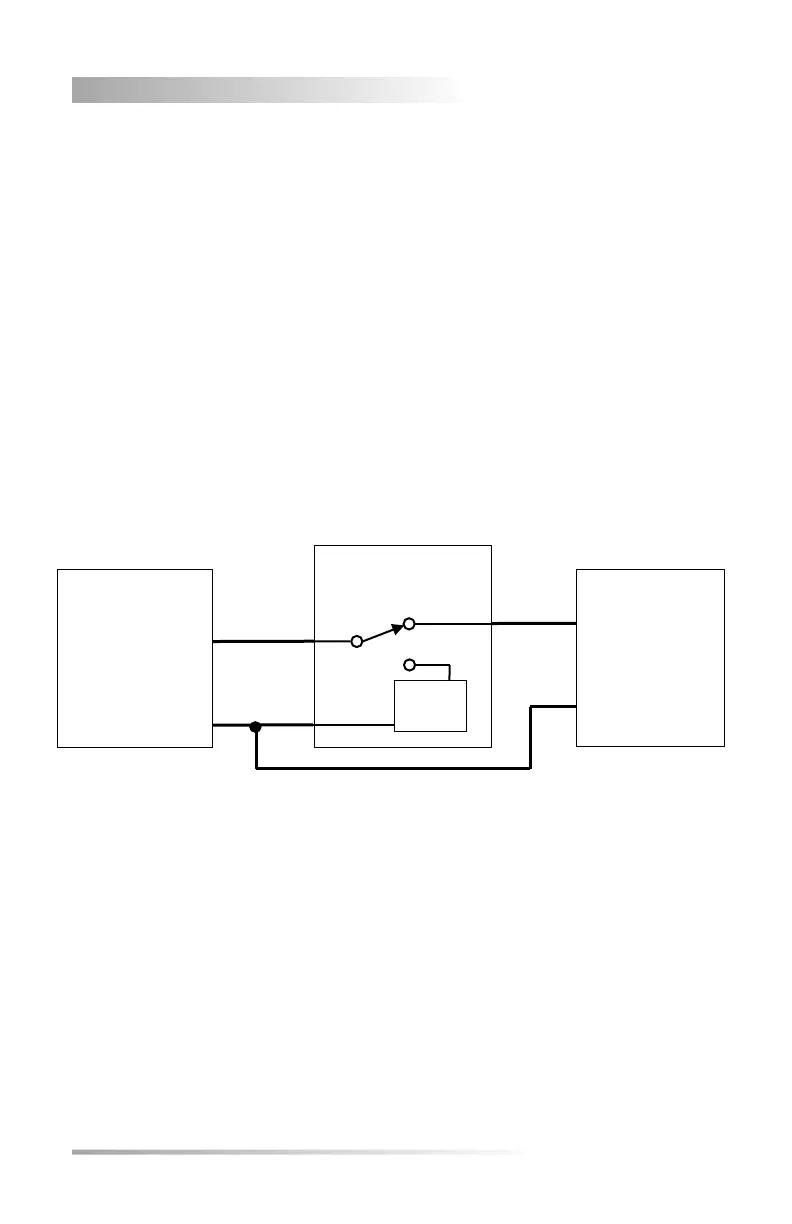
The Dimming Module provides 3 independent channels of 0-10V/DALI control signals
for use in Emergency Lighting. A simplified block diagram of one channel is as follows:
During normal operation, the DIMMABLE EMERGENCY FIXTURE is connected directly
to the DIMMER OR CONTROL through the DIMMER MODULE’s internal signal relay.
Upon loss of power or during a system test, the DIMMER MODULE’s internal relay
changes state so that the User Presets (5 presets 100% - 20%) will assume control of the
dimming level for the DIMMABLE EMERGENCY FIXTURE.
The DIMMER MODULE is not to be used for line voltage and is only intended for low
voltage signals less than 20 VDC, 200 mA. User Presets are reverse-polarity protected
and do not source current – they can only sink current.