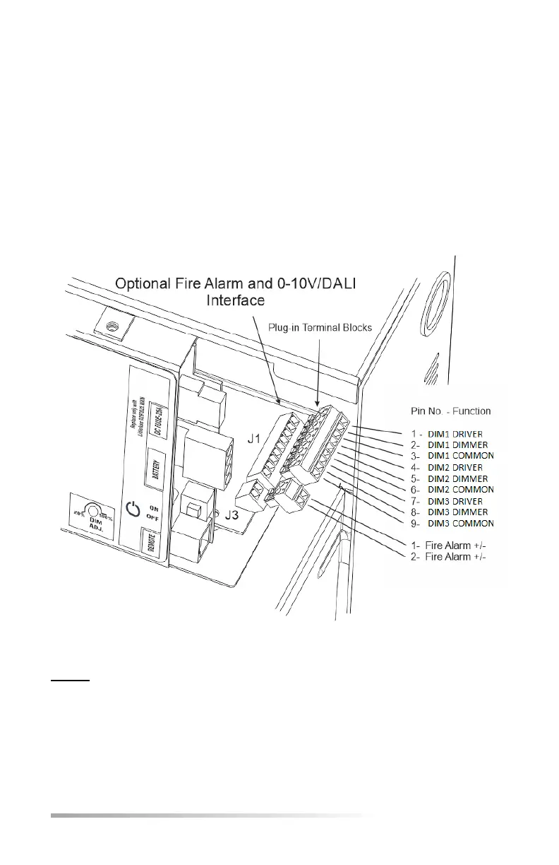
12.4 Fire Alarm/Dimming Connections
For convenience, the manufacturer provides removable connectors for both the
dimming and the fire alarm interface. These connectors allow easier wiring for the
installer since it can be terminated outside the equipment and then plugged in.
For the Fire Alarm function, apply 12-24V AC/DC to the 2 position connector J3. For
the Dimming Interface connect DALI/0-10V violet wires into the connector J1 – please
observe DRIVER and DIMMER positions on the terminal block since this matters when
using any dimming level other than 100%.
DRIVER is connected to the DIMABLE EMERGENCY FIXTURES, DIMMER is connected
to the DIMMING OR CONTROL signal. Please see section 12.2 for detailed signal flow.
NOTE - DALI interface requires the DIM ADJ. to be in the furthest Clockwise (CW) so
that the relay opens during Inverter Mode of operation. Dimming requires a DALI signal
which the E3MINI Series does not provide.