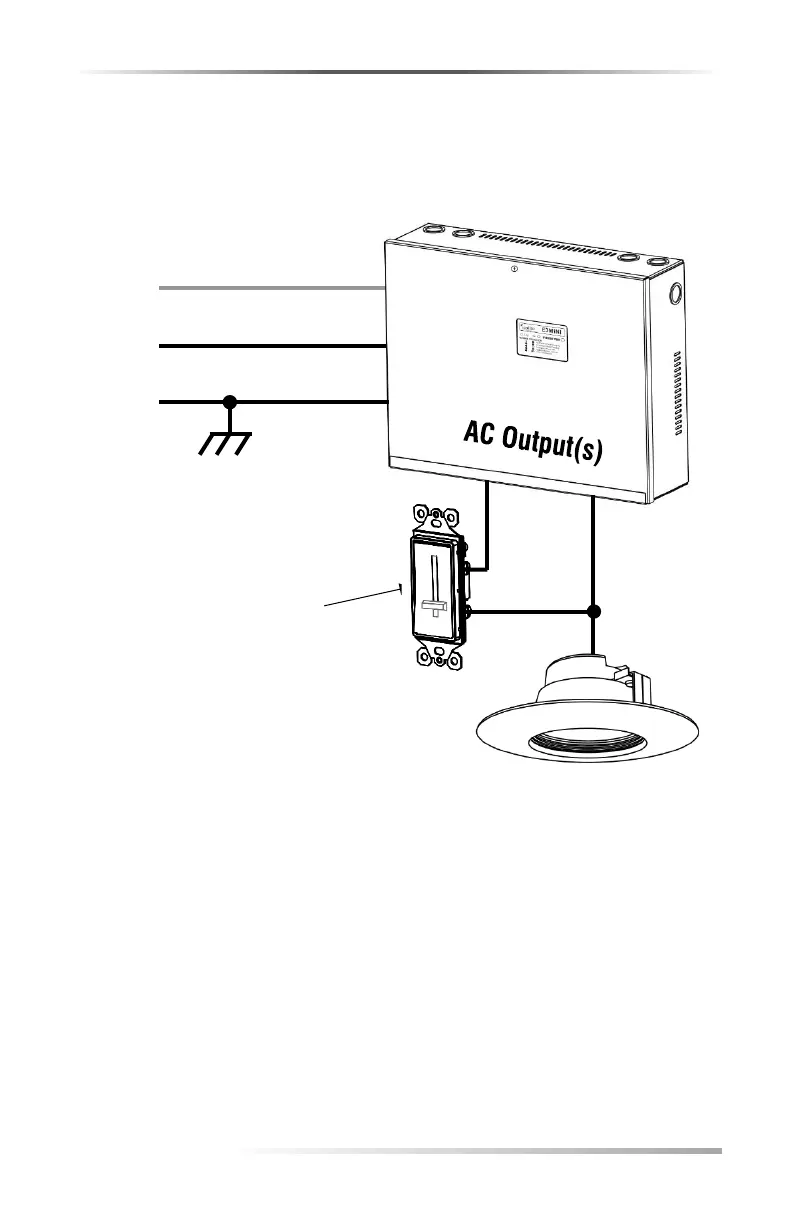
Wiring Diagram Using Line Voltage Dimming
Use when line dimming from Normally-On and bypass with OUT 1,
OUT 2 or OUT 3 during Inverter Mode
Line Voltage DIMMER
Operation:
Inverters Normally-On output (N-ON)
provides power to the LED Fixture in
Normal Mode through the dimmer.
During Emergency Mode, OUT 1, OUT
2 or OUT 3 can wrap around the
dimmer and bypass it.
Note:
LED Fixture Neutral wire not shown.
Always run dedicated hot and
neutral wires to emergency fixtures
per NEC code.
Caution:
Do not overload or back-feed the
inverter with this type of
configuration.