2. Operation
The refrigerators are available in two versions, standard
with mechanical thermostat and optionally in ASU version.
CR 42 and CR INOX cannot be equipped with ASU.
Tem perature regulation for both systems are described
separately below.
The refrigerators are made for use at ambient tempera-
tures between 32°F and 113°F.
2.1 Temperature regulation thermostat
The refrigerator is fi tted with a manually operated
thermostat. This is turned clockwise to reduce
temperature and anti-clockwise to both increase
temperature and activate the on-off switch at the end
position, 0-position. A certain spring resistance is
recognized at the off position.
It is advisable to start with the thermostat in a medium
position. It is advisable to keep a temperature of 41-43°F
inside the refrigerator. Higher temperatures will reduce
storage time.
The ambient temperature infl uences the temperature also
inside the fridge. Avoid direct sunshine and other heat
sources close to the refrigerator.
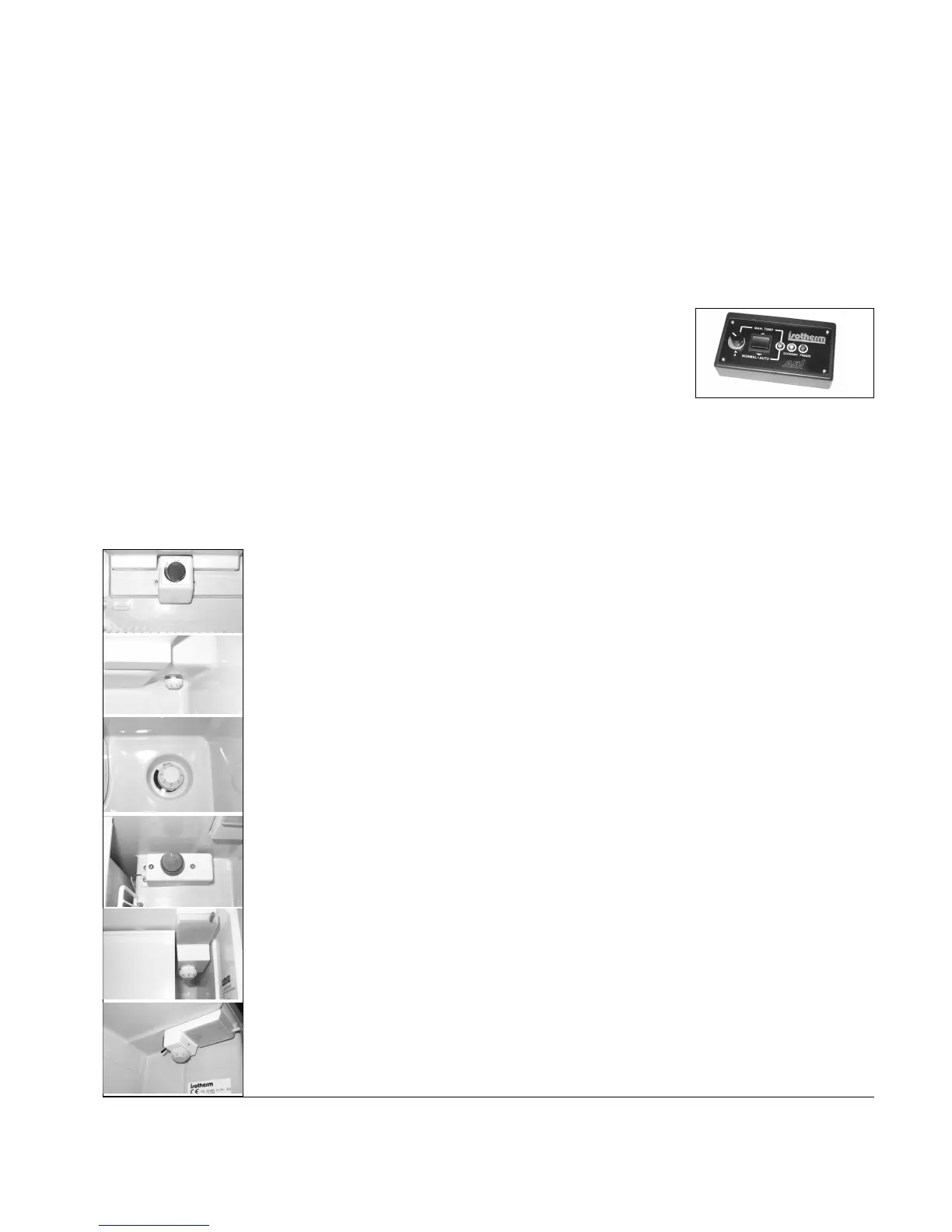
The thermostat control knob is placed inside the
refrigerator, see description below.
2.2 Temperature setting ASU
The Isotherm refrigerators with ASU can be operated
in two ways. When energy saving is needed, switch to
”NORMAL.AUTO” position.
Optimal refrigeration temperature is than automatically
maintained while consuming the lowest amount of
battery power possible. When there is no need of energy
saving, switch to “MAN.TEMP” position on the panel.
The automatic function is now partially blocked and
refrigeration temperature can be manually adjusted. In its
centre position, the unit is switched off. The panel should
be positioned were it easily could be seen. Control cable
length is 4 m (13 ft.). Behind the panel a hole of ½” must be
drilled for the cable.
NORMAL.AUTO position
- The green light indicates that power is being supplied and
the refrigeration programme is activated.
- When the engine is running and the voltage supply
(measured at the electronic unit) is above 13.2 (26.4)
volt, the compressor starts to supply cooling energy to
the holding plate. It starts within the fi rst 30 seconds and
operates fi rst at low speed with the yellow “Economy”
indicator lit.
After less than half a minute, the speed of the compressor
and the fan increase by 75% and the red «Freeze» indicator
light comes on. This operation condition is maintained until
the holding plate is completely frozen at approximately 7°F.
This can take 20 to 40 minutes depending on the model,
ambient temperature and refrigerator size. On reaching
this temperature, the compressor stops and the red light
goes out. When the temperature of the holding plate rises
to 14°F the compressor restarts to charge the holding plate
and the red light comes on again. This process is repeated,
keeping the holding plate at its optimum effi ciency level.
When the engine is stopped, the compressor also stops
shortly afterwards.
When the engine is stopped and the battery voltage is
below 12.7 (25.4) volt, the surplus of refrigeration energy
stored in the holding plate is used fi rst.
Only when this has been consumed does the compressor
start. The yellow light indicates that it is now running, in
the fi rst hand, at its low ”Economy” speed to ”top-up”
the holding plate only and maintain the refrigeration
temperature. This condition starts when the temperature of
the holding plate rises to 30°F and stops when it reaches
economy level of 21°F.
MAN.TEMP position
This position can be used either when shore-power or
solar panels are being used or when energy saving is not
required and a higher or lower refrigerator temperature
is desirable for some reason. The automatic function is
partially blocked, the temperature regulated by means
Thermostat in CR 42,
on rear wall below freezer
compartment.
Thermostat in CR 49, inside on
horizontal wall at the rear.
Thermostat in CR 65,
inside on the rear wall to the
right.
Thermostat in CR 85 & CR
130, inside to the right behind
the light.
Alternative position in the light
housing, for CR49, 65, 85 &
130.
Thermostat in CR 130 Drink,
inside integrated in the light
housing.
3



 To Next Page