EasyManuals Logo

iSystem iC5000 Hardware Reference

iSystem iC5000
69 pages
To Next Page IconTo Next Page
To Previous Page IconTo Previous Page
Page #42 background imageLoading...
Page #42 background image
iSYSTEM, October 2016 42/69
The following pinout is valid on the target side:
Signal direction
Signal
Pin
Pin
Signal
Signal direction
I
MSEO0
1
2
VTREF
I
MSEO1
3
4
TCK
O
GND
5
6
TMS
O
I
MDO0
7
8
TDI
O
I
MDO1
9
10
TDO
I
GND
11
12
NTRST
O
I
MDO2
13
14
RDY
I
MDO3
15
16
EVTI
O
GND
17
18
EVTO
I
I
MCKO
19
20
RESET
I/O
I
MDO4
21
22
NC
GND
23
24
GND
I
MDO5
25
26
NC
I
MDO6
27
28
NC
GND
29
30
GND
I
MDO7
31
32
NC
I
MDO8
33
34
NC
GND
35
36
GND
I
MDO9
37
38
NC
I
MDO10
39
40
NC
GND
41
42
GND
I
MDO11
43
44
MDO13
I
I
MDO12
45
46
MDO14
I
GND
47
48
GND
I
MDO15
49
50
NC
50-pin Samtec ERF8 Nexus target connector pinout
Blue colored signals are required for trace.
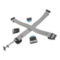
The adapter connects to the target via a 50-pin ERM8 connector (for example SAMTEC: ERM8-025-01-L-D-
EM2-TR). A target should feature a matching part (for example SAMTEC: ERF8-025-05.0-L-DV).

Other manuals for iSystem iC5000

Questions and Answers:

Question and Answer IconNeed help?

Do you have a question about the iSystem iC5000 and is the answer not in the manual?

iSystem iC5000 Specifications

General IconGeneral
BrandiSystem
ModeliC5000
CategoryMeasuring Instruments
LanguageEnglish

Related product manuals