7
4. NOMENCLATURE AND FUNCTIONS
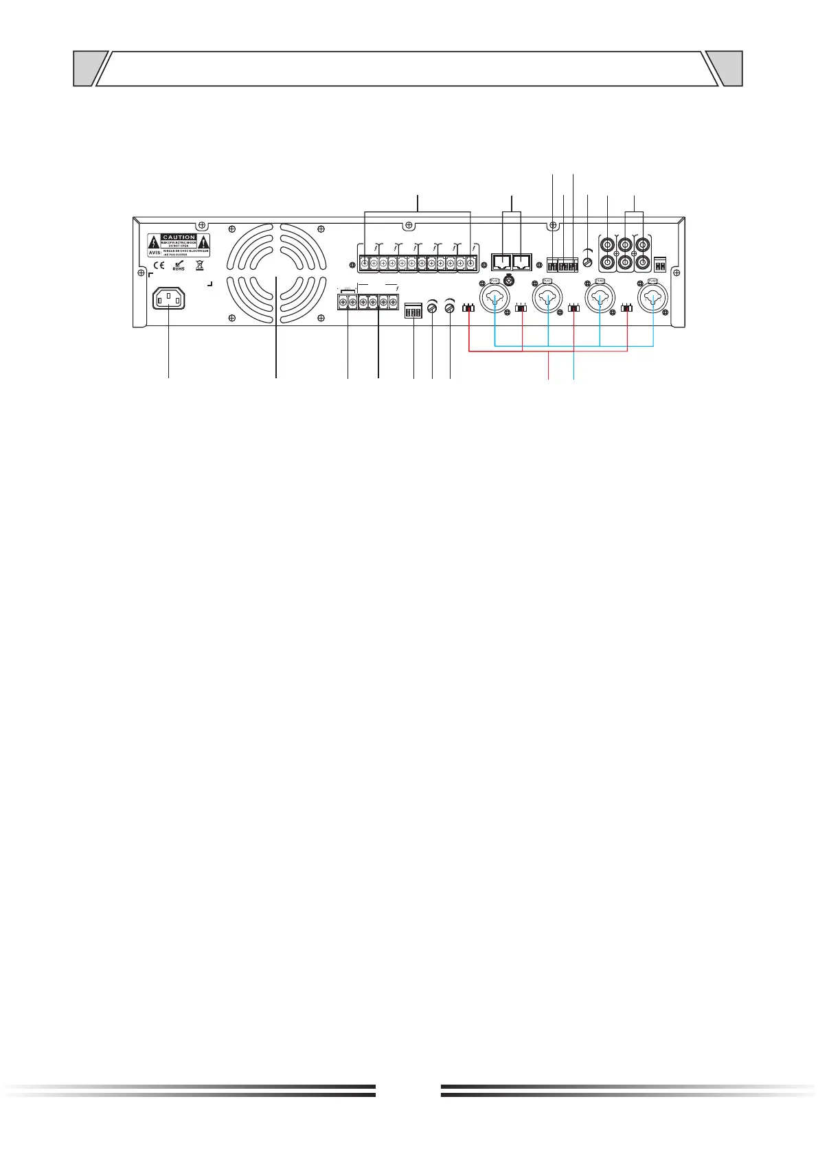
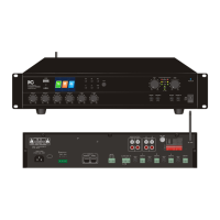
4.3 REAR PANEL
1. The AC power input socket
2. The cooling fan
3. Spare (battery) power connector
4. 4~16Ω / 70V / 100V Speaker output port,
Connecting the speaker terminal. COM is for public terminal which could be connected
with negative terminal and the ground wire. 4~16Ω terminal is used to connect the speaker
with impedance 4~16Ω; 70V terminal is used to connect the speaker with 70V; 100V
terminal is used to connect the speaker with 100V.
5. Alarm /Chime trigger control interface
6. Chime volume control
7. Alarm volume control
8. MIC1 / MIC2 / MIC3 / MIC4 line / microphone / phantom power switch
9. MIC1 / MIC2 / MIC3 / MIC4 balanced input port
10. Two-way line input interface, used to connect the line output interface
11. Line output interface, used to connect the line input interface
12. Telephone volume control
13. Telephone signal input port
14. EMC input port
15. Mute input port
16. Remote Microphone Control Port
17. Six-zone 100V speaker output port
REMOTE MIC
MIC 1MIC 2
MIC 3
MIC 4
SIREN
MIC
LINE
PHANTOM
MIC
LINE
PHANTOM
MIC
LINE
PHANTOM
MIC
LINE
PHANTOM
CHIME
TEL
EMC
MUTE
G
+
G
+
TEL
FM ANT
G +
SIREN
CHIME
XLR BAL
1-GND
2-HOT+
3-COLD-
COM
BATT SUPPLY
24V
8A
OUTPUT
100V
70V
COM
4-16Ω
OUT IN
LINE LINE2
IN
LINE1
ZONE
1
COM
100V
ZONE
2
ZONE
3
ZONE
4
ZONE
5
ZONE
6
COM COM COM COM COM
100V 100V 100V 100V 100V
1
2 3
4
5
6
7
8 9
101112141617
1315