System-Related Functions
When 0V is input, the instrument’s On/Off state is switched to Off state.
When 5V is input, the instrument’s On/Off state is switched to On state.
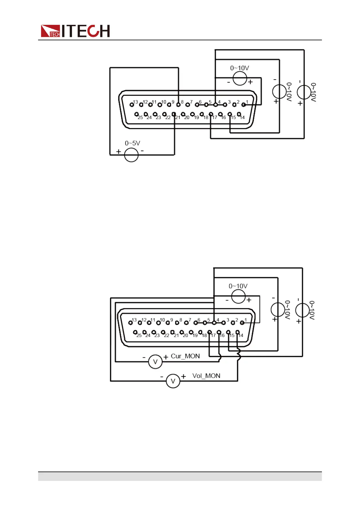
• Voltage and current monitoring
Through the analog interface, the existing output voltage/current or input
voltage/current can be monitored. Connect a digital voltmeter between pin
14 (Vol_MON), pin 16 (Cur_MOM) and ground wire 3/4/5/6 (AGND) of the
analog interface. Other analog input pins should also be connected cor-
rectly. The wiring method is shown in the figure below. The 0 ~ 10V voltage
reading corresponds to the power/load voltage and current output/input be-
tween zero and full scale. The wiring diagram is shown in the figure below.
Copyright © Itech Electronic Co., Ltd.
89