Quick Start
Copyright ©ITECH Electronic Co., Ltd. 8
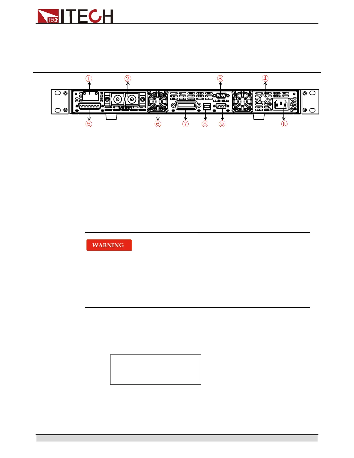
2.5 Rear Panel Introduction
IT6500 series power supply different models are not the same rear board. the detail rear
board schematic graph of the power supply are shown as below.
①
remote sense and ouput terminals
②Output terminal
③RS485 communication interface
④Fuses
⑤Analog control interface
⑥Cooling fans
⑦
GPIB communication interface
⑧USB communication interface
⑨RS232 communication interface
⑩AC power input socket
2.6 Power-on selftest
A successful selftest indicates that the purchased power product meets delivery standards
and is available for normal usage.
Before operation, please confirm that you have fully understood the safety instructions.
To avoid burning out, be sure to confirm that power voltage matches with supply
voltage.
Be sure to connect the main power socket to the power outlet of protective grounding.
Do not use terminal board without protective grounding. Before operation, be sure
that the power supply is well grounded.
To avoid burning out, pay attention to marks of positive and negative polarities before
wiring.
Selftest steps
Normal selftest procedures:
1. Correctly connect the power cord. Press Power key to start up.
2.
After selftest, VFD display the output voltage and current status as below:
Error Information References
The following error information may occur when an error occurs during Power On
self-test:
0.000V 0.000A