SCPI Status Register
Copyright © ITECH Electronic Co., Ltd. 13
Chapter2 SCPI Status Register
SCPI protocol supports the following four groups of registers.
Questionable Status Register Group
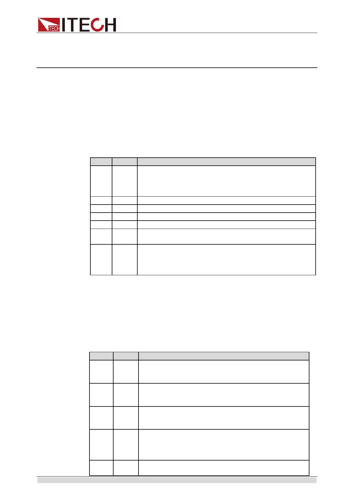
Questionable status register group includes three 16-bit registers: status
register, event register and enable register. When the corresponding status
register bit is changed, the corresponding bit in the event register is set. If the
corresponding bit in the enable register bit is set, it will be generated once
Event (status byte register QUES is set). After executing an event register read
operation, the event register will be automatically cleared. The status register is
defined as follows:
Either an overvoltage or a reverse voltage has occurred
This bit reflects the active state of the FLT pin on the back
of the unit. The bit remains set until the condition is
removed and PROT:CLE is programmed.
An over-current condition hasoccurred.
An overpower condition has occurred.
An over-temperature condition has occurred.
Remote measurement terminal is not connected.
The input is unregulated, when the input is regulated the bit
is cleared.
An over voltage condition has occurred. Both this bit and
VF bit0 are set and the loads are turned off. Both bits
remain set until the condition is removed and PROT:CLE is
programmed.
Standard Event Status Register Group
The standard event register group consists of two 16-bit registers: the event
register and the enable register. When an event occurs, and if the
corresponding bit in the enable register is set, an event occurs (the ESB in the
Status Byte register is set). After executing an event register read operation, the
event register will be automatically cleared. The event register is defined as
follows:
The load has completed all pending operations. *OPC
must be programmed for this bit to be set when pending
operations are complete.
The output queue was read with no data present or the
data was lost. Errors in the range of 499 through 400 can
set this bit.
Device-Dependent Error. Memory was lost or self test
failed. Errors in the range of 399 through 300 can set this
bit.
A command parameter was outside its legal range,
inconsistent with the load's operation, or prevented from
executing because of an operating condition. Errors in
the range of 299 through 200 can set this bit.
A syntax or semantic error has occurred or the load
received a <get> within a program message. Errors in