Inspection and Installation
Copyright © Itech Electronic Co., Ltd. 3
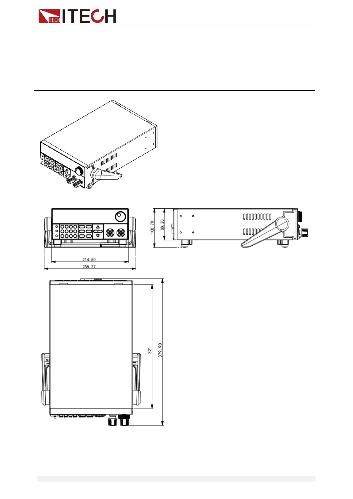
1.2 Instrument Size Introduction
The instrument should be installed at well-ventilated and rational-sized space.
Please select appropriate space for installation based on the electronic load
size.
IT8500+ series electronic load different models are not the same size, the detail
size of the electronic load is shown as below.