Copyright © ITECH Electronic Co., Ltd. 11
1.4 Connecting Test Lines
Precautions When Wiring the Circuit
⚫ To prevent electric shock, turn the circuit under measurement off before
connection.
⚫ Always put the mains plug into the grounded socket. Never use an ungrounded
wiring board. Before connecting the circuit, make sure the electronic load is
grounded properly.
⚫ Strip the insulation covers of the measurement cables so that when they are
wired to the input terminals, the conductive parts (bare wires) do not protrude
from the terminals. Also, make sure to fasten the input terminal screws
securely so that cables do not come loose.
⚫ When connecting measurement cables to the input terminals, only connect
measurement cables that have safety rubber terminals that cover their
conductive parts. Also, make sure to fasten the input terminal screws securely
so that cables do not come loose.
⚫ Use measurement cables satisfying the rated conditions and with dielectric
strengths and current capacities that are appropriate for the voltage and
current being measured.
⚫ Example: when making measurements on a current of 20A, use copper wires
that have a conductive cross-sectional area of 4mm
2
or greater.
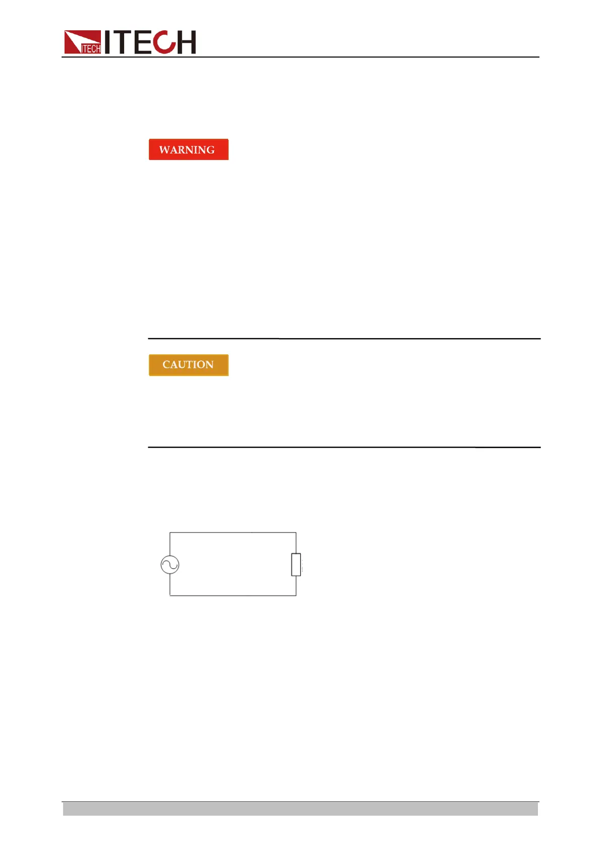
Connecting the Measurement Circuit
IT8600 electronic load can measure electrical parameters of the test object. The
specific circuit connection diagram is shown below.
⚫ The wiring for basic measurements of Model IT8615/IT8615L/IT8616 (side
plate structure)/IT8617 (side plate structure and 15U cabinet: three masters)
is as follows.
1. Respectively connect drive wires to six terminals Vs+/ V+/ V+ and Vs-/
V-/V- of the rear panel.
2. Respectively connect the other ends of wires to the anode and cathode
of the test object (as shown below).
ООО "Техэнком" Контрольно-измерительные приборы и оборудование www.tehencom.com