64
Annex 6: Transmitters / Emetteurs / Polung der Anschlüsse / Emettitori d’impulsi / Emisores / Connector
aansluiting / Vericiler / Transmissores
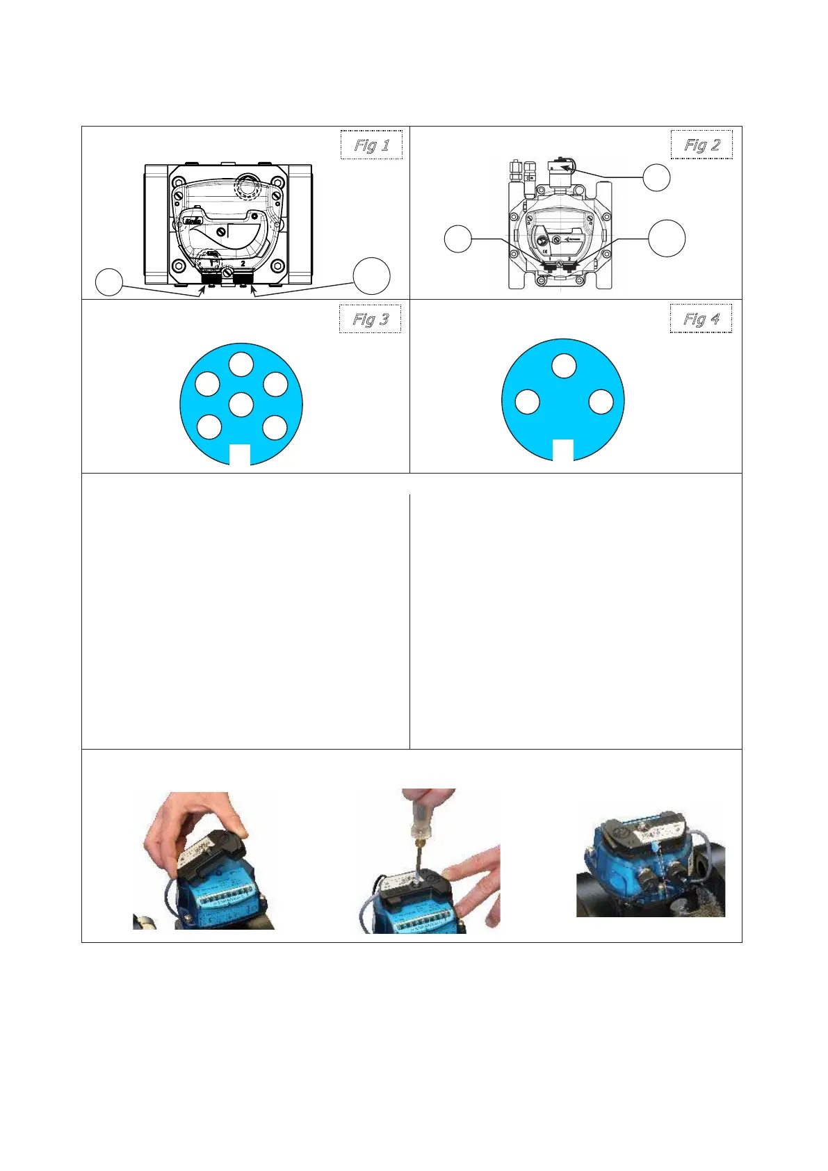
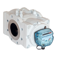
Compact DN25/DN40/DN50 DN50/DN80/DN100/DN150
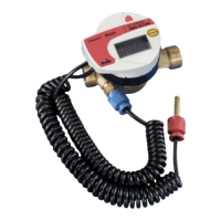
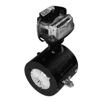
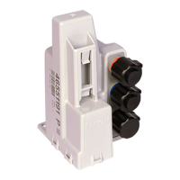
Binder plug 6 pins (LF, MF, HF) Binder plug 3 pins (HF)
(Rear view of the plug) (Rear view of the plug)
Unless on the nameplate noted the following electrical parameters shall be considered:
Low Frequency transmitters (LF):
1) Internal Reed contacts characteristics
• Hermetically sealed contacts
– Maximum terminal voltage: 30 Volt and maxi-
mum current according to EN 60079-11.
• Ambient temperature Ta= -30°C to +60°C
• Minimum pulse time: 0,4 s
2) Cyble sensor
• It conforms to CENELEC standard
EN 60079-11 with:
– Ui ≤ 14,3 Volt
– Ii ≤ 50 mA
Inductive transmitters:
High & medium frequency transmitters cha-
racteristics
• Proximity detectors conform to EN
60947-5-6 (NAMUR) standard.
• They conform to CENELEC standards
(EN 60079-0 and EN 60079-11)
with:
– Ui ≤ 16 Volt
– Ii ≤ 52 mA
– Ci ≤ 50F
– Li ≤ 250μH
– Pi ≤ 64 mW
Ambient temperature Ta= -30°C to +60°C
Installation of the Cyble sensor
1) Mounting 2) Screwing (Max torque: 0,25Nm) 3) Sealing
Note: For the plugging of the LF, HF and anti-tampering, please report to the name plate of the meter.
LF,
MF
LF,
HF
HF
LF
LF