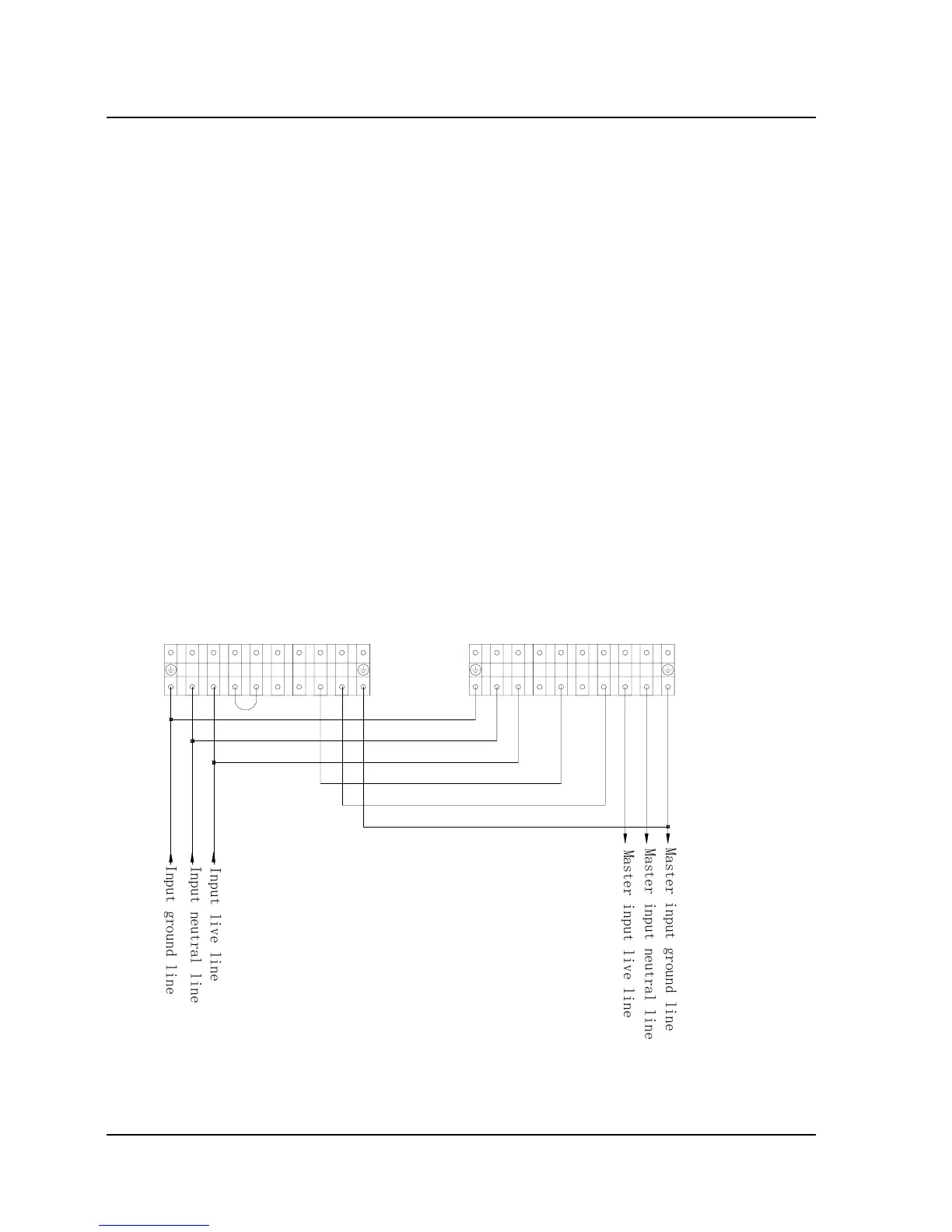
2.3 Wiring of Master/Slave Hot Standby System
1. Be sure that the input circuit breakers of the master UPS and
slave UPS are all in the OFF position, and neither UPS has output;
2. Remove the shorting stub between the hot standby L terminal and
B terminal of the master UPS. Retain it, as it may be used in the
future;
3. Perform wiring as shown in Fig. 2-6.
Note: Make sure that the neutral lines, live lines and ground lines
are correctly and reliably connected. In the case of master/slave hot
standby system adopting long backup time UPS, the master UPS
and the slave UPS should have separate external battery, i.e. They
can not share the same external battery.
Slave output live line connected to Master bypass
I
n
p
u
t
g
r
o
u
n
d
l
i
n
e
N
L
L
B
+
_
L
N
Slave
Output ground lines in parallel
Master
N
L
L
B+
_
L
N
Input live lives in parallel
Input neutral lines in parallel
Input ground lines in parallel
Slave neutral line connected to battery input terminel(-)
I
n
p
u
t
n
e
u
t
r
a
l
l
i
n
e
I
n
p
u
t
l
i
v
e
l
i
n
e
M
a
s
t
e
r
i
n
p
u
t
l
i
v
e
l
i
n
e
M
a
s
t
e
r
i
n
p
u
t
n
e
u
t
r
a
l
l
i
n
e
M
a
s
t
e
r
i
n
p
u
t
g
r
o
u
n
d
l
i
n
e
Fig. 2-6 Wiring Diagram of 6kVA/10kVA Master/Slave Hot Standby System
20 Chapter 2 Installation
E1-20010916-C-1.0