ITW Dynatec c. 2004
DYNAMINI ASU Manual #20-25
Page 8-1
Revised 1/05
To Remove the Pump & Electronics Cover
(See illustration on page 10-7)
1. Loosen the four captive screws (two on each
side) along the bottom of the pump and elec-
tronics cover.
2. Lift the cover straight up and out of its slots
in the base.
To Remove the Hopper Cover
(See illustration on page 10-7)
1. Loosen the two captive screws along the
bottom of the hopper cover.
2. Remove the access cover screw, then lift the
access cover out of its slots in the base.
3. Remove the screw that attaches to the heat
shield.
4. Remove the two screws that attach the back
panel to the hopper cover.
5. Lift the hopper cover up and out of its slots
in the base.
Chapter 8
DISASSEMBLY & RE-ASSEMBLY PROCEDURES
Disassembly Procedures
Note: Re-read Chapter 1 “Safety Precautions” before performing any disassembly procedures. All
dissassembly procedures must be performed by qualified, trained technicians.
When needed, cross-reference the exploded-view component drawings in Chapter 10 with each pro-
cedure in addition to the instructions and illustrations given in this chapter. Read the
“Cautions” on page 8-7 before re-assembling the ASU.
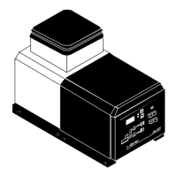
Pump & electronics cover
Pump access cover
Hopper cover
Captive screw
Captive screw