Design and Function
14
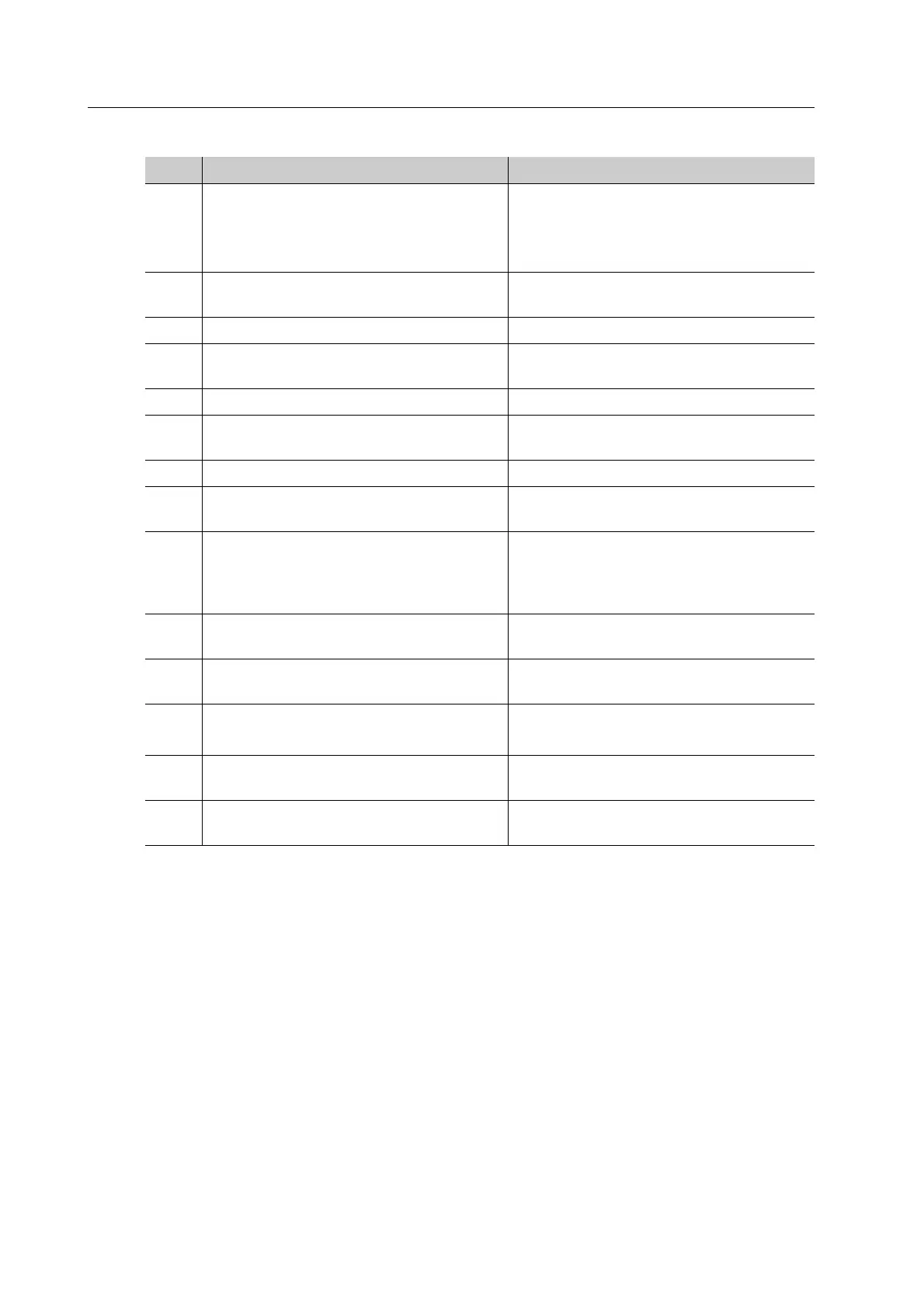
No. Description Function
1 Pull-out shelf with indentations (in the
illustration part of the front panel has
been faded out for better visibility)
• Holds the PrograMill Suction Unit
• The indentations ensure proper
positioning of PrograMill Suction
Unit
2 Exhaust air outlet Removal of exhaust air to the
PrograMill Suction Unit
3 Service wheels Only for the service partner
4 Drawer Storage of tools, discs / blocks and
cleaning agents
5 Storage space Position for the milling machine
6 Indentations for device feet Secure positioning of the milling
machine on the PrograMill Base
7 Tube and cable access Cable and tube guides
8 Handle Pulling the shelf out and pushing it
back in
9 Tube holder The water outlet tube and the water
inlet tube are attached in the tube
holder during cleaning and
maintenance work
10 Lock Securing the pull-out shelf against
unwanted movement
11 Device feet Height adjustment of the PrograMill
Base cabinet
12 Energy chain • Laying cables and tubes
• Kink protection for cables and tubes
13 Wheels Pulling the shelf out and pushing it
back in
14 Crossbeam Ensures the stability of the PrograMill
system