12LRN
2 – 8
1.9. Peak control
If the current flowing in the air to air heat pump exceeds the peak con-
trol current the operation frequency is decreased until the current
value drops below the peak control current regardless of the frequency
control demand issued from the indoor unit based on the room temper-
ature.
1.10. Outdoor unit fan delay control
The compressor stops immediately after cooling, dehumidifying or
heating operation is shut down, but the outdoor unit fan continues
operation for 50 seconds before it stops.
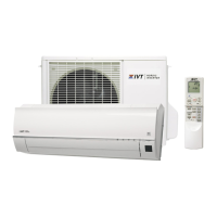
1.11. Defrosting
1.11.1 Reverse defr osting
The defrost operation starts when the compressor operating time
exceeds 20 minutes during heating operation, as shown below, and
the outside air temperature and the outdoor unit heat exchanger tem-
perature meet certain conditions. When the defrost operation starts,
the indoor unit fan stops. The defrost operation stops by the state of
cyde temperature or the defrosting time exceeds 6 minutes.
1.12. ON timer
The ON timer can be activated by pressing the ON timer button. When
the ON timer is activated, the operation start time is adjusted based on
fuzzy logic calculations 1 hour before the set time so that the room
temperature reaches the set temperature at the set time.
1.13. OFF time r
The OFF timer can be activated by pressing the OFF timer button.
When the OFF timer is set, the operation stops after the set time.
When this timer is set, the compressor operating frequency lowers for
quieter operation, and the room temperature is gradually varied after
one hour (reduced 1C three times (max. 3C) in heating, or increased
0.3C three times (max. 1C) in cooling or dehumidifying operation) so
that the room temperature remains suitable for comfortable sleeping.
1.14. Power ON start
If a jumper cable is inserted in the location marked with HAJP on the
indoor unit control printed circuit board (control PCB), connecting the
power cord to an AC outlet starts the air to air heat pump in either cool-
ing or heating mode, which is determined automatically by the room
temperature sensor.
When a circuit breaker is used to control the ON/OFF operation,
please insert a jumper as described above.
1.15. Self-diagnostic malfu nction cod e display
1.15.1 Indoor unit
1) When a malfunction is confirmed, a flashing malfunction code num-
ber is displayed to indicate the type of malfunction.
When the air to air heat pump is in non-operating condition, holding
down AUX button for more than 5 seconds activates the malfunc-
tion code display function.
The operation continues only in the case of a serial open-circuit,
and the main relay turns off after 30 seconds if the open-circuit con-
dition remains.
In the case of a serial short-circuit, the air to air heat pump contin-
ues operating without a malfunction code display.
The malfunction information is stored in memory, and can be
recalled later and shown on display.
2) The self-diagnostic memory can be recalled and shown on the dis-
play by stopping the operation and holding down AUX button for
more than 5 seconds.
3) The content of self-diagnosis (malfunction mode) is indicated by a
flashing number.
(For details, refer to the troubleshooting section.)
1.15.2 Outdoor unit
If a malfunction occurs, LED1 on the outdoor unit flashes in 0.2-sec-
ond intervals as shown below.
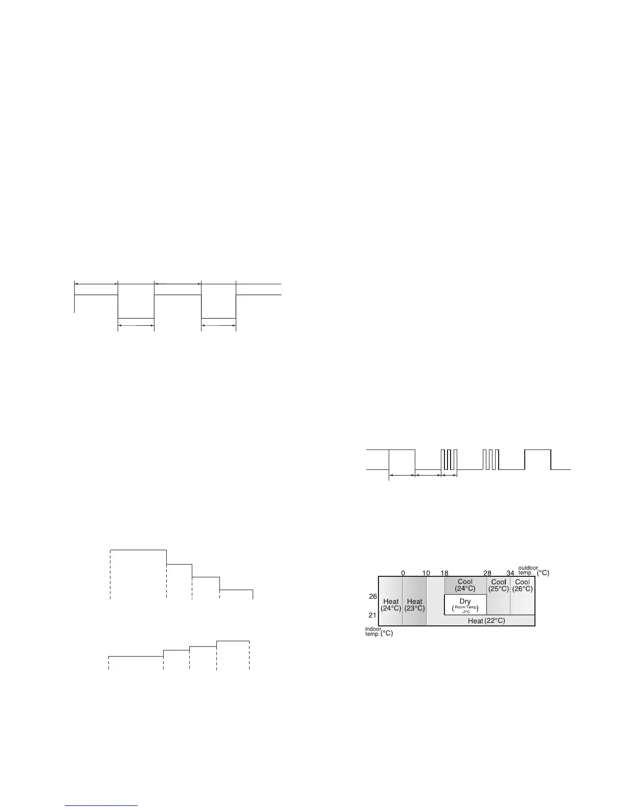
1.16. Information about auto mode
In the AUTO mode, the temperature setting and mode are automati-
cally selected according to the room temperature and outdoor temper-
ature when the unit is turned on.
During operation, if the outdoor temperature changes, the temperature
settings will automatically slide as shown in the chart.
20 min or more 6 min or more 6 min or more
Defrosting
Max. 10 min
Defrosting
Max. 10 min
Start of
heating
operation
Heating operation
Set temperature
Activation of
OFF timer
1 hour
later
Max.
1.5 hours
later
Max.
2 hours
later
Timer setting
reached
1 hour
later
Max.
1.5 hours
later
Max.
2 hours
later
Timer setting
reached
Activation of
OFF timer
Set temperature
-1
O
C
-1
O
C
-1
O
C
0.3
O
C
0.3
O
C
0.3
O
C
Cooling/dehumidifying operation
1 sec 1 sec 0.6 sec
ON
OFF
(Example) Compressor high temperature abnormality
Modes and Temperature Settings
the figures in ( ) are temperature settings
 Loading...