12LRN
3 – 8
9. Operation stops after a few minutes and restarts, and this process repeats
CAUTION: If fuse FU1/FU4/FU5 (outdoor unit control circuit board) is blown, be careful of charging voltage in inverter electrolytic capacitor C9, C10.
To discharge stored electricity, unplug the power cord and connect the plug of a soldering iron (230VAC, 50W) between the positive and
negative terminals of inverter electrolytic capacitor C9, C10.
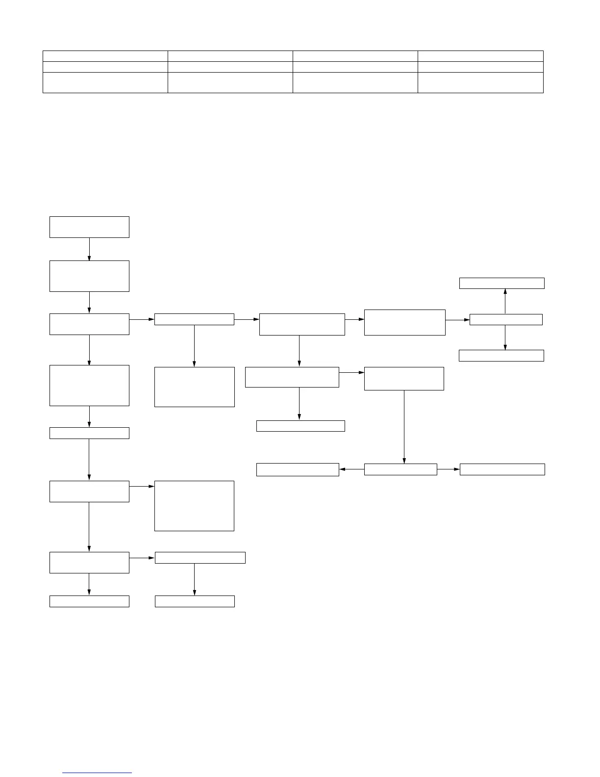
[6] MALFUNCTION (PARTS) CHECK METHOD
1. Procedure for determining defective outdoor unit IPM/compressor
The following flow chart shows a procedure for locating the cause of a malfunction when the compressor does not start up and a DC overcurrent indi-
cation error occurs.
CAUTION: Please take care for electrical shock when you work to change defective parts or disconnect wires of defective application.
The outdoor unit has energy changed for a while even after unplugging the power supply cord.
After changing the part or unit, please retry check procedure from the beginning.
Main cause Inspection method Normal value/condition Remedy
Dried-up electrolytic capacitor. Measure 320VDC line voltage. 300 V or higher. Replace electrolytic capacitor.
Layer short-circuit in expansion
valve coil.
Measure resistance. 463 in each phase (at 20C) Replace coil.
YES
Immediately
after startup
YES
YES
NO
NO
NO
YES
NO
Connect power cord
to AC outlet.
Normal
Using remote control,
operate air conditioner
so that compressor
starts.
Check 220-240 VAC
between (1) and (N)
on outdoor unit PWB.
Is LED1 on outdoor
unit flashing?
Compressor starts up.
Does LED1 indicate
DC overcurrent error?
Does LED1 indicate
rotation error?
Replace compressor.
Does LED1 remain lit?
Serial signal error.
Check inter-unit wiring.
Check indoor and
outdoor unit PWBs.
Replace outdoor unit
PWB.
Check compressor.
2/3-way valve closed.
Refrigerant shortage.
Replace outdoor unit PWB.
Check 320 VDC between
pins IPM (20) and (24)?
LED1 is flashing.
Replace outdoor unit PWB.
Replace expansion valve.
Disconnect (CN3) lead
wires of FAN motor.
Disconnect (CN12)
expansion valve.
Replace outdoor unit PWB.
YES
NO
YES
NO
NO
YES
YES
No
(unlit)
FUSE and+12 V, +15 V,
+18V on PWB
(LED1 is still off)
Replace outdoor unit PWB.
Replace FAN motor.
LED1 is flashing.
YES
NO