AYXP12JHRN
5 – 7
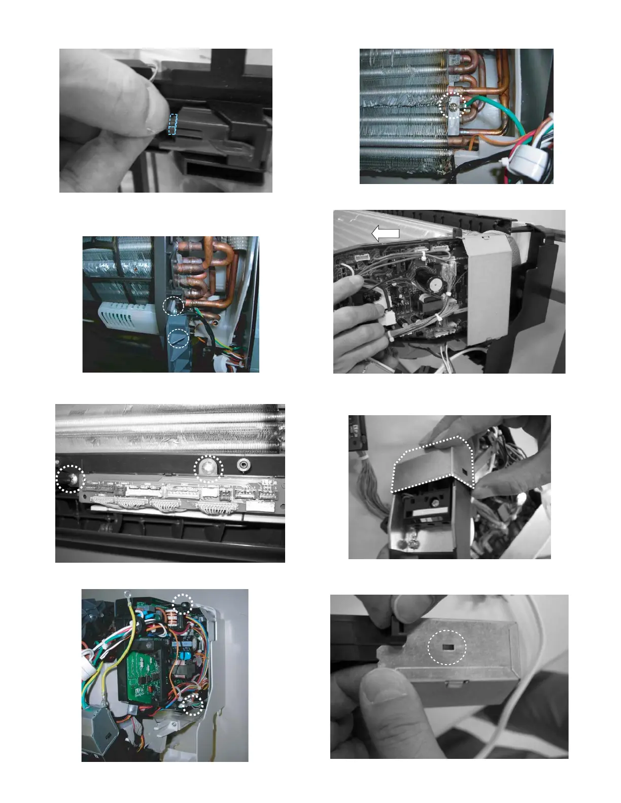
47)The wire connector of the limit switch is removed.
48)The thermally sensitive resistor holder is removed.
(Hook two places)
49)The relay printed bord holder removed. (2 screws)
50)P.W.B. assmbly is removed. (2 screws)
51)The earth cable is removed. (1 earth screw )
52)The P.W.B.assembly is drawn out forward.
53)The Terminal cover of the Terminal stand assembly is removed.
(Hook two places)
54)The P.W.B. box cover is removed. (Hook one place) And the con-
trol bord unit is removed.
 Loading...