Commissioning
Vent 402 – 6721815546 (2021/03)
15
Commissioning should be done only after filling. Please, proceed first
with the Filling (chapter 6.1) and only then initiate the Commissioning
of the heat pump’s control unit (chapter 6.2 ). At last, perform the
Purging process (chapter 6.3).
6.1 Filling
If the heating circuit is already installed with shut off valves, these can be
closed to keep the water in the heating circuit and fill the heat pump
separately.
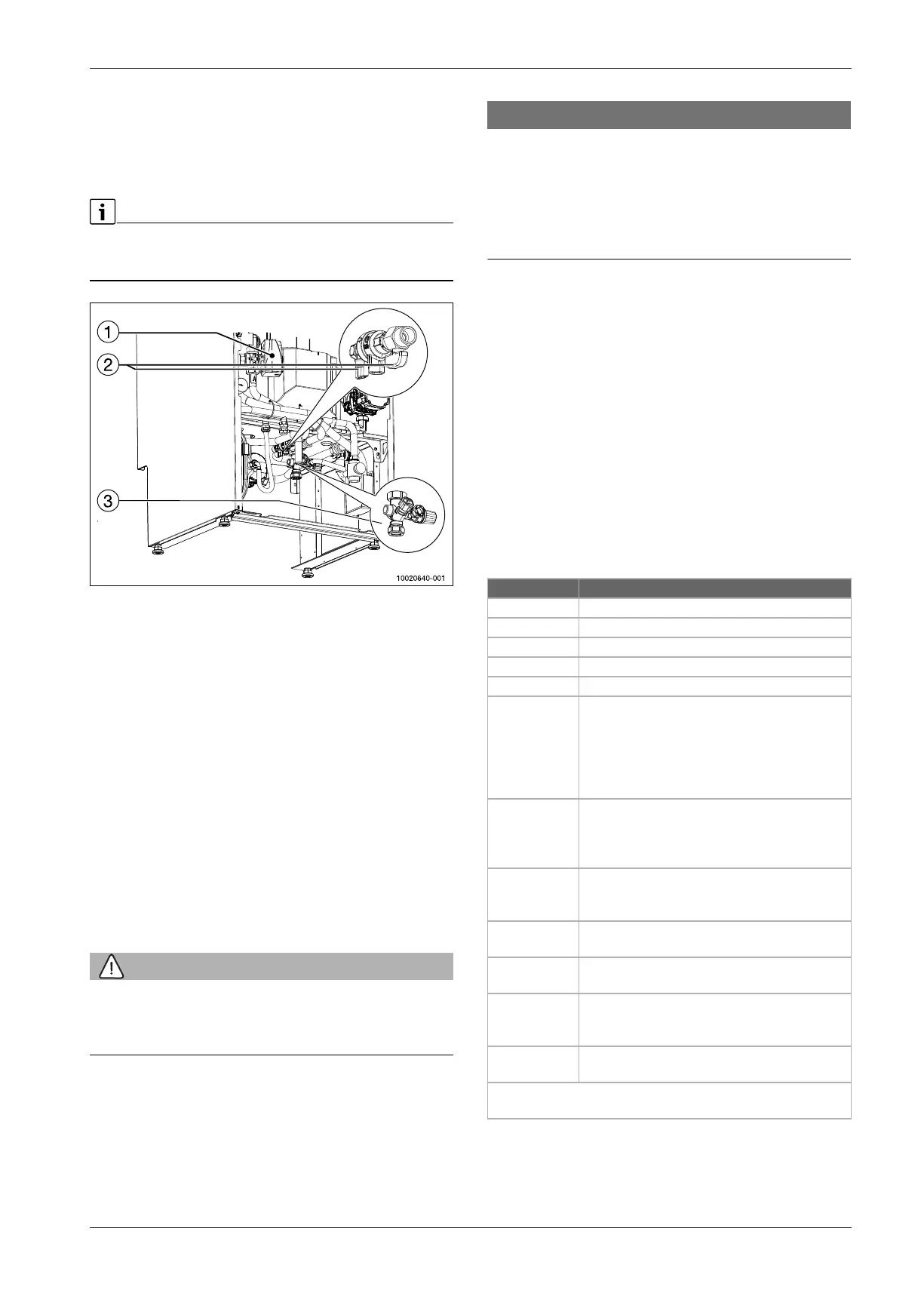
Fig. 19 Hydraulic connections area
[1] Diverter valve
[2] Filling valves
[3] DHW filling valve
Filling procedure:
Fill the DHW tank: Open one DHW end user tap outlet and the tap
water inlet in the filling link. When there is water coming out of the
end user tap the tank is full. Close the end user tap.
Ensure all air vent valves are open: in refrigerant box; on electrical
heater and on primary circuit pump.
Ensure the diverter valve is in position A (central heating position
which is the default position from factory). Check Fig. 3.
Open the filling valve until the pressure raises to 2.5 bar.
If the central heating system is also being filled check all manual vent
valves.
6.2 Commissioning of the control unit
This user interface has a touch display, use your finger to swipe between
the menus and tap to make settings. The user interface controls up to a
maximum of 2 heating circuits.
WARNING
Risk of scalding!
As DHW temperatures above 60 °C can be reached when the customer
activates the extra DHW function, a temperature mixing device must be
installed.
NOTICE
Floor damage!
The floor may be damaged due to excessive heat.
For underfloor heating systems, make sure that the maximum
temperature for the floor type in question is not exceeded.
If necessary, connect an additional temperature switch at the voltage
input of the respective circulation pump and to one of the external
inputs.
Overview of the commissioning steps
1. Coding of the modules (observe instructions of the modules).
2. Make sure the complete heating system is filled with water.
3. Switch on the system.
4. Do the first time commissioning of the Rego 3000 user interface
( Chapter 6.2.1).
5. If necessary, do further commissioning steps according to chapter
6.2.1.
6. Check and, if necessary, adjust the settings in the service menu
( Chapter 7.7).
7. Remedy warning and fault displays and reset fault history.
8. System handover ( Chapter 6.8).
6.2.1 Commissioning of the control unit for the first time
The first time the control unit is connected to voltage, a configuration
wizard starts. The display switches to the default screen when the wizard
is finished.
Table 7 Configuration wizard
Menu item Description
Language Set the language.
Date format Set the date format.
Date Set the date.
Time of Day Set the time.
Country Set the country.
Min. outdoor
temperature
Set the design temperature for the system, DUT
(Dimensioning outdoor temperature). This is the
lowest average outdoor air temperature for the
region. The setting affects the slope of the heat
curve, as it is the point where the heat source
reaches the highest flow temperature.
Only DHW
Production
This setting is used when replacing an older exhaust
air heat pump with a smaller electric heater
1)
.
Select [Yes] for DHW mode only.
Select No if there is also a heating system installed.
1) This menu appears only if the code switch is set to P = 2.
Exhaust air heat
recovery
installed
Select [Yes] whether a supply air heater has been
installed. Otherwise choose No.
Heating system
HC1
Radiators | Convectors | Radiant floor heating:
Setting the type of heat distribution.
Max. temp non
floor HC1
2)
2) Alarm limit, make sure that the heat curve end point is set at a lower temperature.
For [Radiators] or [Convectors]: Set the maximum
flow temperature for heating circuit 1 and confirm.
Max. temp floor
HC1
For [Radiant floor heating] heat distribution: Set the
maximum flow temperature for heating circuit 1 and
confirm.
Fuse
3)
3) This menu appears only if an output limiter is installed.
16 A | 20 A | 25 A | 32 A: Adjust the main fuse as is
intended for the heat pump.
Store installer settings: Exit the configuration wizard by clicking
[Finish].