Installation
Vent 402 – 6721815546 (2021/03)
9
5.3.2 Hydraulic connections
CAUTION
Risk of scalding!
The maximum DHW temperature can be set above 60 °C and during
thermal disinfection the DHW is heated to >60 °C.
Only carry out thermal disinfection outside normal hours of use.
Inform all people concerned and make sure that a mixing device is
installed.
NOTICE
Damage to system due to negative pressure in the DHW cylinder.
If a difference in height of ≥ 8 metres between the DHW outlet and the
drainage point is exceeded, a negative pressure leading to deformation
of the DHW cylinder may occur.
Avoid differences in height of ≥ 8 metres between the DHW outlet
and drainage point.
Install an anti-vacuum valve if the difference in height between the
hot water outlet and drainage point is ≥ 8 metres.
If the heat pump has been transported in freezing temperatures it is
recommended to wait with the installation of the leakage water pipe until
after other pipe connections have been made, so that the waste water
cup has time to be heated by the room air.
To simplify installation where space is limited, flex hoses can be used for
connections between the heat pump and heating/DHW systems.
Connect according to 11.
Connect a 32 mm pvc pipe from the leakage water container to the
floor drain.
Fig. 11 Pipe connection front view
[1] Inlet domestic cold water
[2] Outlet domestic hot water
[3] Outlet central heating
[4] Return central heating
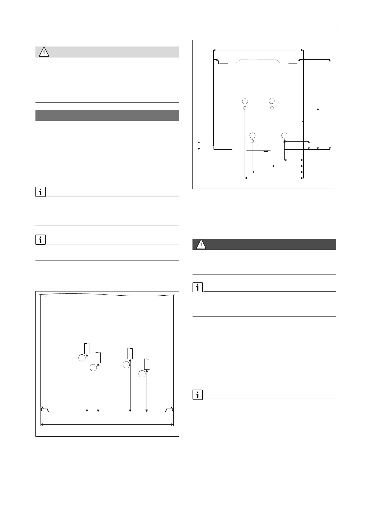
Fig. 12 Pipe connection top view
[1] Inlet domestic cold water
[2] Outlet domestic hot water
[3] Outlet central heating
[4] Return central heating
5.3.3 Electrical connections
DANGER
Risk for electrical shocks
The heat pump components conduct electricity.
Turn off the main power before performing any electrical work.
The heat pump's electrical connection must be safely interruptable.
Install a separate safety switch which disconnects all current to the
heat pump.
If the safety switch cannot be installed on a wall, it can instead be
installed in the heat pump. A special accessory is available for this.
Connect the outdoor temperature sensor. Take into account the
consideration on graph 13.
Connect the power supply to the unit according to the diagrams.
Ensure to install a residual current device based on normative
requirements in each country. We recommend to use residual current
device type B.
Outside temperature sensor T1
A shielded cable must be used if the outside temperature sensor cable is
longer than 15 m. The screened cable must be grounded in the inside
unit. The max. length of a screened cable is 50 m.
If the temperature sensor cable has to be extended, the following wire
diameters should be used:
• Up to 20 m long cable: 0.75 to 1.50 mm
2
• Up to 30 m long cable: 1.0 to 1.50 mm
2
The cable to the outside temperature sensor must meet the following
minimum requirements:
• Cable diameter: 0.5 mm
2
2
3
1
4
600
262
221
240
192
10020638-002
600
391
341
209
126
600
277
55
60
1
43
2
10020732-002