Technical information
Vent 402 – 6721815546 (2021/03)
35
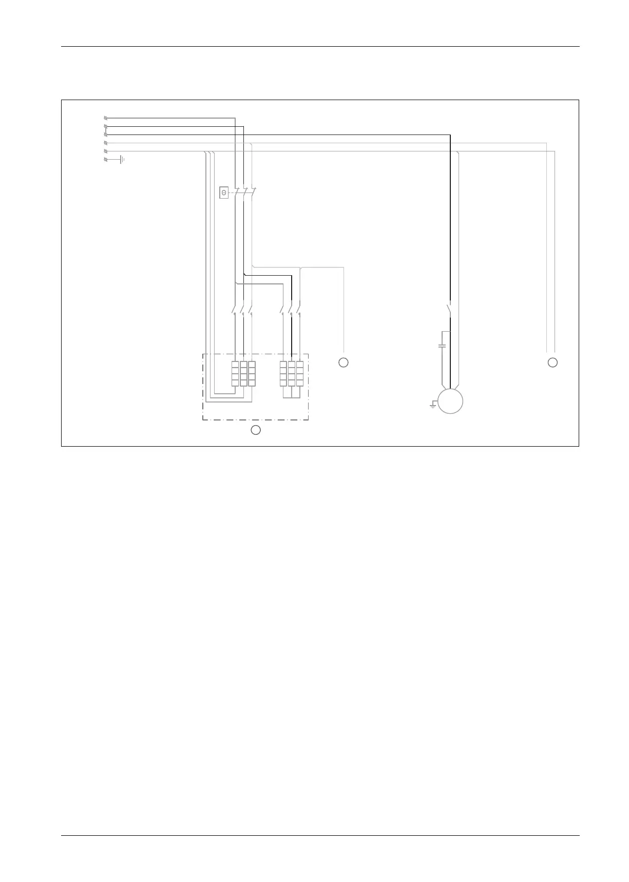
12.11 Wiring diagram
12.11.1 400 V, 3N ~ 50 Hz 13.5 kW
Fig. 46 Wiring diagram main circuit, 400 V 3N 13.5 kW
[1] Immersion heater alarm
[2] ~ 230 V control voltage
[3] Immersion heater: 4.5-9-13.5 kW
[EE] Booster heater cassette
[ER1] Compressor
[FE] Overheating protection of immersion heater
[K1] Contactor power step 1 (EE1)
[K2] Contactor power step 2 (EE2)
[K3] Relay start compressor
1112
2122
3132
2
FE
SRN
M
ER1
Cr
K3
L1
L2
L3
N
2L2
400V 3N
~
PE
EE
4,5 kW 9 kW
1
35Ω
18Ω
(3x1,5kW) (3x3kW)
K1 K2
12
3
4
5
6
12
3
4
5
6
L1
L2 L3
3
0010028309-003