Installation
Vent 402 – 6721815546 (2021/03)
10
• Resistance: max. 50 ohm/km
• Number of conductors: 2
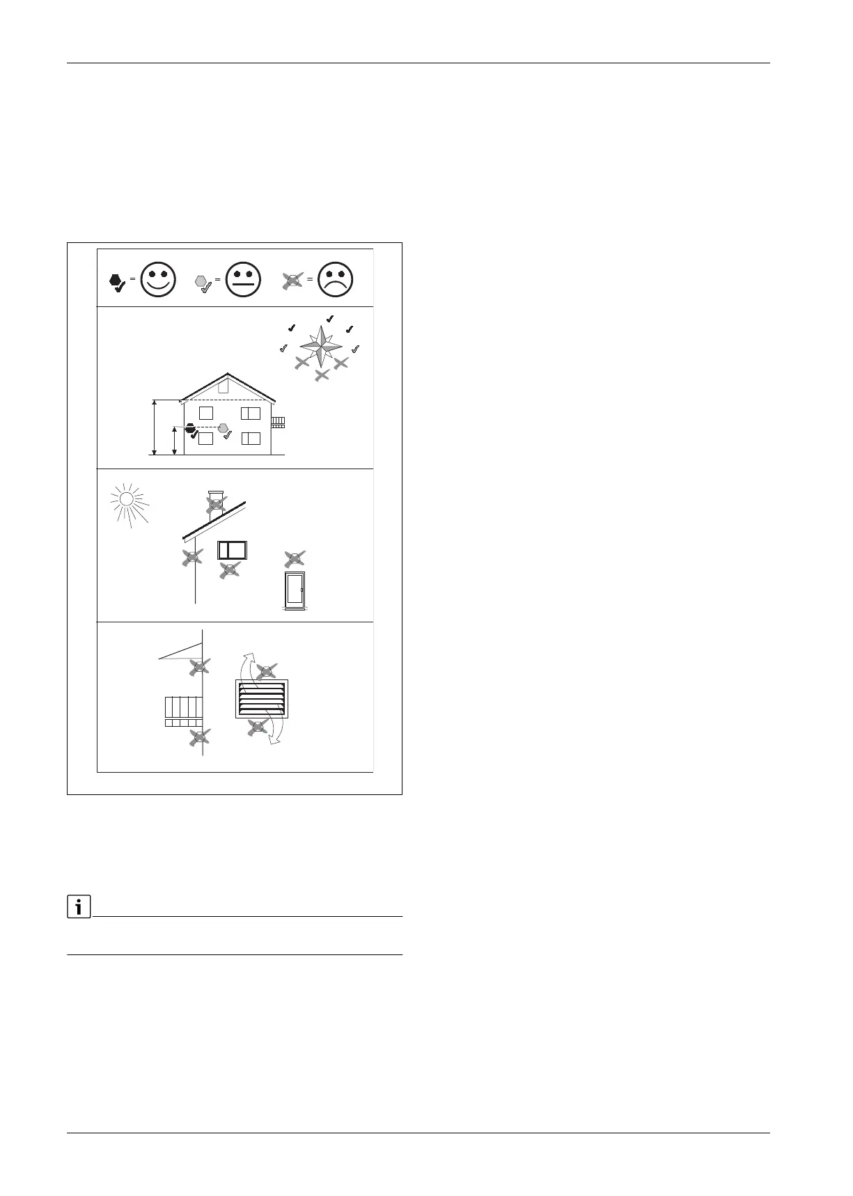
Mount the sensor on the coldest side of the house, normally facing
north. The sensor must be protected against direct sunlight,
ventilation air or other factors which could affect temperature
measurement. The sensor may not be installed directly under the
roof.
Connect the outdoor temperature sensor T1to the terminal T1 on the
installer module.
Fig. 13 Outside temperature sensor positioning
External connections
To avoid inductive interference, all low-voltage conductors (test current)
should be drawn with a minimum space of 100 mm from current-
carrying 230 V and 400 V cables.
Max utilisation relay outputs: 2 A, cos At a higher utilisation, an
intermediate relay is mounted.
1
/
2
H
(min 2m)
H
N
S
W
E
NW
NE
SW
SE
6 720 809 156-23.1I