Installation
Vent 402 – 6721815546 (2021/03)
11
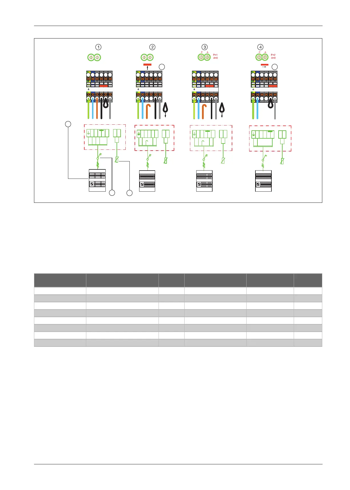
Fig. 14 External connections 1-9 kW
[1] Incoming feed 400 V 3N ~, 3/6/9 kW immersion heater
[2] Incoming feed 400 V 2N ~, 1 kW immersion heater
[3] Incoming feed 400 V 2N ~, 2 kW immersion heater
[4] Incoming feed 230 V 1N ~, 1 kW immersion heater
[5] Notice! Remove the jumper
[6] Notice! Place the jumper
[7] Electrical Box
[8] Safety switch
[9] Outside temperature sensor
Table 4 Possible power limitation configurations
10017261-009
N
L1
L2
L3
9kW, 400V 3N
~
Inst.-modul
4
3
T1
2L2
0
1
2
3
4
8
A
B
D
F
5
6
7
9
C
E
0
1
2
3
4
8
A
B
D
F
5
6
7
9
C
E
PA
P=1
A=0
1kW, 400V 2N
~
Inst.-modul
4
3
T1
0
1
2
3
4
8
A
B
D
F
5
6
7
9
C
E
0
1
2
3
4
8
A
B
D
F
5
6
7
9
C
E
PA
P=1
A=0
N
L1
L2
L3
2L2
2kW, 400V 2N
~
Inst.-modul
4
3
T1
N
L1
L2
L3
2L2
1kW, 230V 1N
~
Inst.-modul
4
3
T1
N
L1
L2
L3
2L2
N
L2
L1
L3
2L2
9
8
7
5
6
N
L2
L1
L3
2L2
N
L2
L1
L3
2L2
N
L2
L1
L3
2L2
Performance heat
limitation [kW]
Bevel setting and electrical
connection
P encoders Menu: Electrical mode Menu: Only DHW
Production
Fuse Power
1 kW
1)
1) The configuration is equivalent to IVT 550 with only hot water production
Picture 14 [4] 2 - Yes 10
1 kW
2)
2) Configuration is equivalent to IVT 590 / 595
Picture 14 [4] 2 - No 10
1 kW
3)
3) The configuration is applicable when IVT 490 / 690 replaced
Picture 14 [2] 1 1 kW - 10
2 kW
3)
Picture 14 [3] 1 2 kW - 10
3 kW
3)
Picture 14 [1] 1 3 kW - 10
6 kW
3)4)
4) 6 kW alternative requires the installer to set HMI menu option: Red. 6 kW
Picture 14 [1] 1 3-stage - 16
9 kW
3)
Picture 14 [1] 1 3-stage - 16
9 kW
3)
Picture 14 [5] 1 3-stage - 25