This document outlines the user manual for the FDM-615PTM device, a robust solution for drone HD video downlink applications, supporting 2x2 MIMO and Point-to-Multipoint (PtMP) communication over distances of 100km to 150km. The manual details hardware interfaces, software operations, AT commands, and case configurations, providing a comprehensive guide for setup, operation, and maintenance.
Function Description
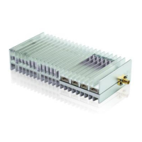
The FDM-615PTM is designed for reliable high-definition video downlink from drones, facilitating long-range, stable communication. It supports 2x2 MIMO (Multiple-Input Multiple-Output) technology, enhancing data throughput and link reliability, and PtMP (Point-to-Multipoint) configurations, allowing a central node to communicate with multiple access nodes simultaneously. This makes it ideal for applications requiring video transmission from several drones to a single ground station. The device operates as a wireless modem, enabling the transmission of data streams, including HD video, over significant distances. It features both central node and access node functionalities, with specific configurations for each role within a network. The central node acts as the hub, managing communication with all connected access nodes, which are typically installed on drones.
The device's core function revolves around establishing and maintaining a stable wireless link for data transfer. It supports various uplink and downlink configurations (e.g., config0(2D3U), config1(3D2U), config2(4D1U), config3(1D4U)), allowing users to optimize bandwidth allocation based on their specific application needs, where 'D' denotes Downlink and 'U' denotes Uplink. This flexibility is crucial for scenarios where either more downlink capacity (for video streaming) or more uplink capacity (for control signals) is required. The device also incorporates frequency hopping capabilities, which can improve resistance to interference and enhance link stability in challenging RF environments.
Important Technical Specifications
- Communication Range: 100km-150km, suitable for long-distance drone operations.
- MIMO Configuration: 2x2 MIMO, providing improved data rates and link robustness.
- Network Topology: Point-to-Multipoint (PtMP), allowing one central node to connect with multiple access nodes.
- Video Transmission: Supports HD video downlink.
- Power Input: DC+24V.
- Ethernet Port: 10/100M Ethernet Port (PH2.0-4: RX1-, RX1+, TX1-, TX1+).
- Serial Data Interface: Full duplex RS232 data (PH2.0-3: COM-R, GND, COM-T).
- Antenna Connector: SMA type.
- Frequency Bands: Supports 800M, 1.4G, and 2.4G frequency bands, with configurable frequency points (e.g., 24015-24814, 8060-8259, 14279-14478).
- Bandwidth Options: Configurable bandwidths, including 20M.
- IP Address: Initial IP address is http://192.168.1.XX. Default IP addresses are 192.168.1.3/24 for the central node and 192.168.1.2/24, 192.168.1.4/24 for access nodes.
- Default Login Credentials: User name: admin123, Password: admin123.
- Uplink/Downlink Modes: Four configurable modes: config0(2D3U), config1(3D2U), config2(4D1U), config3(1D4U).
- Data Rate (Mbps): Varies significantly based on bandwidth (1.4MHz, 3MHz, 5MHz, 10MHz, 20MHz) and D/U configuration. For example, at 20MHz, downlink data rates can reach up to 36.43916 Mbps, and uplink data rates up to 37.63389 Mbps, depending on the specific configuration (0, 1, 2, or 3).
- RSRP and SNR Reporting: The device actively reports signal strength (RSRP) and Signal-to-Noise Ratio (SNR) for link quality monitoring. RSRP ranges are categorized (e.g., <-124, -124~-104, -103~-85, -84~-65, >-64), and SNR ranges (e.g., <0, 0~6, 7~12, 13~18, >19).
Usage Features
- WebUI Management Tool: The primary interface for configuring the FDM-615PTM. It allows users to manually select parameters, input relevant settings, and monitor the device's status.
- Key Setting: Before networking, each node requires a key to be entered, ensuring secure communication. The key must be an even hexadecimal number, 0-9, A-F, and no more than 32 bytes.
- Master-Slave Setting: Users can configure a device as either a central node (master) or an access node (slave). Only one central node is allowed per network.
- Wireless Setting: This section allows configuration of the frequency band, frequency hopping, bandwidth, and building chain.
- Network Parameter Setting: Users can set the IP address of the node. The central node's IP address can be modified, and access nodes will automatically adopt the network configuration from the central node.
- Uplink and Downlink Setting: The central node can modify uplink and downlink settings to optimize data flow. Access nodes automatically adjust their configurations based on the central node's settings.
- VCOM Function: This feature can be enabled or disabled via the WebUI.
- Debug Interface: Provides tools for active escalation checks, DRPR (Drone Remote Pilot Report) status, shell command debugging, and AT command debugging.
- Device Information: Displays system, HLSystem, and PHYSystem version information.
- Central-Access Indicator: A visual indicator on the device distinguishes between central (bright) and access (blinking) nodes.
- Ethernet Indicator: Blinks rapidly during self-check and then according to data stream activity during normal operation.
- Signal Strength Indicator: Changes color from green (strong) to yellow to red (weak), indicating signal quality. Off means connection lost.
- Power Indicator: Stays bright when the device is powered on.
- Plug and Play for Access Nodes: Once the central node is configured, access nodes automatically obtain their configuration upon connecting to the network, simplifying deployment.
- NVR Integration: The device supports integration with Network Video Recorders (NVRs) for video monitoring. The NVR can send ARP packets, allowing it to be set with a different subnet network from the FDM-615PTM.
Maintenance Features
- WebUI for Configuration and Monitoring: The WebUI provides a centralized platform for managing all device settings and monitoring its operational status, including signal strength (RSRP), SNR, and device information.
- AT Commands Support: A comprehensive set of AT commands (e.g., AT+CFUN, AT^LCMFUN, AT^DTSET, AT^NETIFCFG, AT^DGMR, AT^DFGMR, AT^RCVR, AT^DAMR, AT^POWERCTL, AT^CAMERATL, AT^RMTCTL, AT^ELFUN, AT^ELCH, AT^ELCFGUL, AT^RECOVSET, AT^APLFUN, AT^VCOMFUN, AT^DHCPSET, AT^DHDRSET) are supported via the AT Debug Interface for advanced configuration and troubleshooting. These commands allow for granular control over various aspects of the device, such as function control, key settings, master-slave configuration, frequency band settings, IP address settings, VCOM function, and frequency hopping.
- Modem Restart Functionality: The WebUI allows for modem restart, which is often required after certain configuration changes (e.g., key setting, master-slave setting, frequency band setting, uplink/downlink setting, frequency hopping setting) to ensure the new settings take effect.
- Factory Settings Restore: The device can be restored to factory settings, which resets the account and password to their initial values.
- Firmware Version Display: The "Equipment Information" section in the WebUI displays the AllSystem Version, HLSystem Version, and PHYSystem Version, which is useful for maintenance and support.
- Debug Interfaces: Dedicated interfaces for active escalation checks, DRPR reports, shell command debugging, and AT command debugging provide tools for diagnosing and resolving issues.
- IP Address Management: The ability to change the IP address of the node and the automatic configuration of access nodes simplify network management.
- Important Notices for Operation: The manual includes critical warnings such as installing antennas before powering on to prevent device damage, maintaining a minimum distance of 10 meters between units for short-distance tests, and ensuring adequate power input (+24V/1.5A) for optimal performance. It also recommends using IE browser (version 11) for Web login.
- Default 2-Layer Routing and Forwarding: The FDM-615PTM defaults to 2-layer routing and forwarding. Users can utilize the default gateway and IP if there are no IP conflicts. If changes to the gateway and IP are needed, they must be updated via the WebUI, followed by a device restart.