CONTROLS 4
en-31
4.2.6.23 CONNECTOR J2 ________________________________________________________
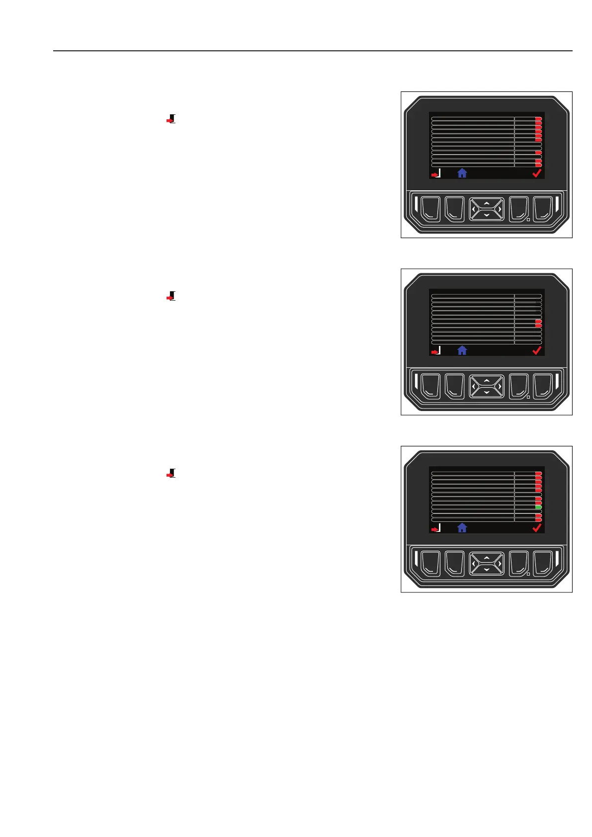
This screen shows the status of the J2 connector circuits.
Press the left side button to return to I/O diagnostics menu.
Values are shown for illustration purposes only.
4.2.6.24 CONNECTOR J3 ________________________________________________________
This screen shows the status of the J3 connector circuits.
Press the left side button to return to I/O diagnostics menu.
Values are shown for illustration purposes only.
4.2.6.25 CONNECTOR J4 ________________________________________________________
This screen shows the status of the J4 connector circuits.
Press the left side button to return to I/O diagnostics menu.
Values are shown for illustration purposes only.
Connector J2
J2-1 Center Lower Solenoid
J2-2 Right Wing Enable Solenoid
J2-3 Center Lift Solenoid
J2-4 Fan Direction
J2-5 Park Brake Solenoid
J2-6 Run w/ Interlocks
J2-7 EDC FWD (mA)
J2-8 EDC REV (mA)
J2-9 Wing Pressure Enable Solenoid
J2-10 Fan Speed (%)
J2-11 Float Solenoid
J2-12 Weight Transfer Pressure Solenoid
O
0
0
O
0
O
O
O
O
O
O
O
Connector J3
J3-1
155.5
85
J3-2 Engine Coolant Temperature
J3-3
J3-4
J3-5 Fuel Sender (%)
J3-6
J3-7 Right Wheel Speed Input
J3-8 Left Wheel Speed Input
J3-9 Signal Ground
J3-10
J3-11 Pedal 1 Input (V)
J3-12 Pedal 2 Input (V)
O
O
0
0
Connector J4
J4-1 Seat Switch
O
J4-2 Center Prox/Cross Cut
J4-3 Left Wing Prox
J4-4 Right Wing Prox
J4-5 Hydraulic Oil Level
J4-6
J4-7 Start Switch
J4-8 Park Brake Switch
J4-9 PTO (Mow) Switch
J4-10
J4-11 Left Wing Enable
J4-12 Right Wing Enable
O
O
O
O
O
O
On
O
O
 Loading...