26
Power Requirements
Jacuzzi spas are designed to provide optimum performance
and exibility of use when connected to the maximum electrical
service listed below. Minor circuit board modications can be
performed to allow your new spa to accept an electrical service
other than the factory operation setting.
Volt 220-230 V ~ Hertz 50
16 A 32 A 16 A
16 A
(a) (b) (c)*
(a) (b) (c)*
(a) (b) (c)*
(a) (b) (c)*
(a) (b) (c)*
(a) (b) (c)*
(a) (b) (c)*
(a) (b) (c)*
J-315
J-325
J-335
J-345
J-355
J-365
J-375
J-385
Ampere
Terminal
Breaker N°
1
2
(*) This is the factory setting.
This operation can only be performed by authorized Jacuz-
zi® technicians and limits electricity consumption as follows:
(a) The heater will not operate while either jets pump is run-
ning.
(b) The heater will operate while two jets pump are running.
(c) The heater will operate while both jets pump are running.
This is the factory setting.
See “Dip Switch Settings” chapter.
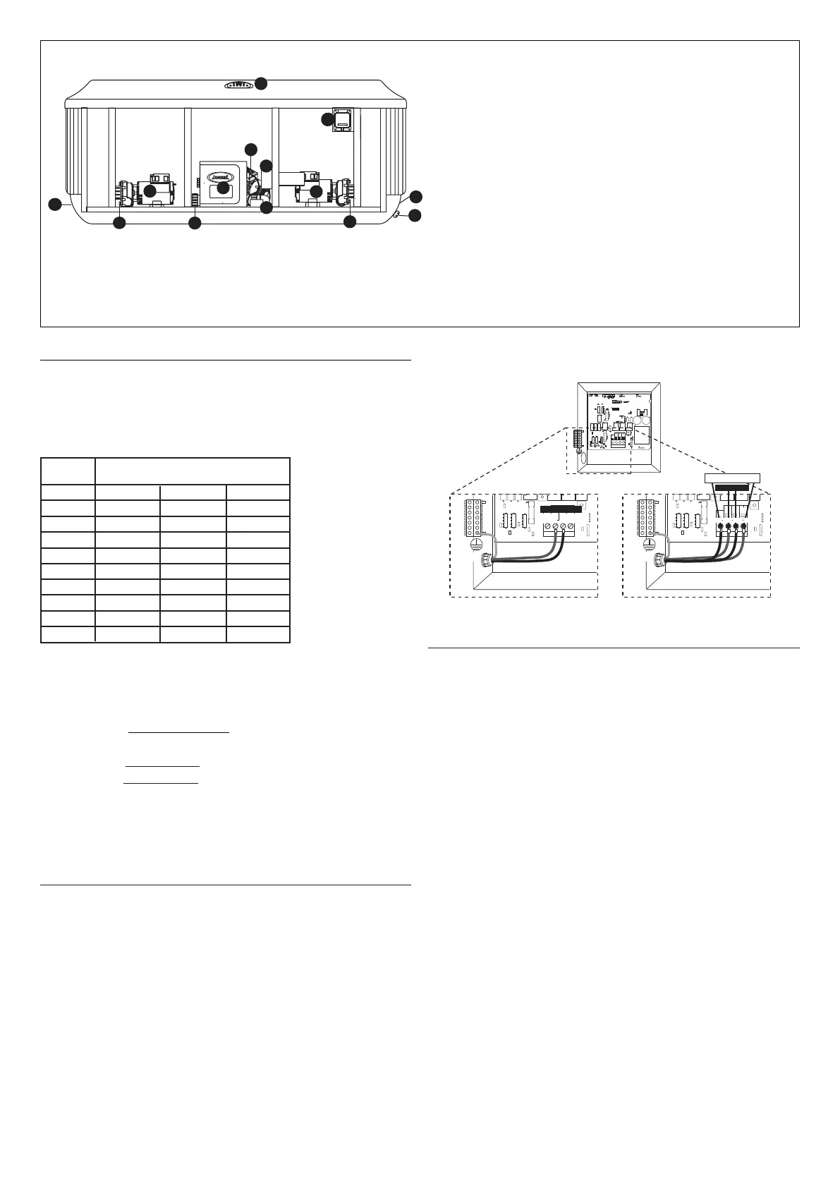
Electrical Wiring Instructions
To gain access to the spa’s power terminal block, press the rele-
ase button securing the cabinet panel under the control panel.
Refer to Section “Draining and Relling” for instructions on how
to remove the cabinet panel(s). Then remove the six door screws
on the control box. Place the panel is a safe location to prevent
damage.
Select the power supply entrance you want to use. Make sure
to install a 3/4" electrical tting and conduit through the large
opening provided in the bottom of the control box so you can
feed the cable through to the terminal block.
Connect wires to the terminal block. ALL WIRES MUST BE SECU-
RELY CONNECTED or equipment damage could result!
Install control access box door and reinstall the cabinet panel(s).
TB3
TB1
A
B
C
D
OZONE
P1 1SPD
UV
A/V
30A
F2 10A 250VAC
F3 0.125A 240V
30A
FAN
STEP LIGHT
(OPTIONAL)
J37
J44
J73
J72
J74
J35
J59
J51
J33
J36 J46
J41 J47
J49
J38
J53
TB3
TB1
A
B
C
D
J37
J44
J73
J72
J74
J35
J33
J36 J46
J41 J47
J49
J38
J53
BrnBlu
TB3
TB1
A
B
C
D
J37
J44
J73
J72
J74
J35
J33
J36 J46
J41 J47
J49
J38
J53
Brn
Blu
Brn
Blu
Monophasée
Monophasée
Biphasée 2
Vert
Vert
Start-up instructions
Read each step in its entirety before proceeding with that
step.
Remove any dirt from the spa. Although the spa shell has
been polished at the factory, you may want to treat it with a spe-
cially formulated spa cleaner and wax available from your dealer
prior to lling the rst time.
Filling the spa
Remove the lter cover, then remove both lter cartridges as
outlined in section “Cleaning The Filters”.
Position the end of the hose inside the lter connection and ll
the spa until the level of water covers all of the nozzles, without
however reaching the headrest.
Do not overll your spa.
N.B.: If your water is extremely hard, it is preferable to ll halfway
with hard water and the rest of the way with softened water.
Always rell the spa through both lter ttings to purge trapped
air from pump intakes. Failure to do so may cause air to be trap-
ped in either pump 1 or the circulation pump’s intake, preven-
ting the pumps from circulating water.
After lling, make sure both lters are installed properly before
applying power to the spa. (refer to sec.) “Cleaning the lters”).
12
5
3
7
2
2
9
6
6
10
11
1
8
4
1 Electrical box
2 Power supply entrance(s)
3 1 Speed Pump (pump 1)
4 Heater
5 Drain valve
6 Pump drain plug(s)
7 1-Speed pump
8 Circulation pump
9 Control Panel
10 CLEARRAY™ (Ultraviolet) Water Purification System
11 Electronic Ballast (for the CLEARRAY™ System)
12 Optional ProLink™ Monitoring System
 Loading...