- 28 -
INST 396 Jacuzzi® J-HN Series Heater V12-16
If pressure switch cannot be adjusted correctly. DO NOT OPERATE THE HEATER, contact Jacuzzi® or an Authorised
Service Agent for advice. If heater is more than 5 feet (1.5 METERS) above or more than 1 foot (300MM) below the level of
the pool/spa water line (measured from pressure switch to water line), you are exceeding the range of the pressure switch
and a FLOW SWITCH MAY BE REQUIRED. The flow switch replaces the pressure switch and is wired to pressure switches
wiring.
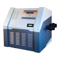
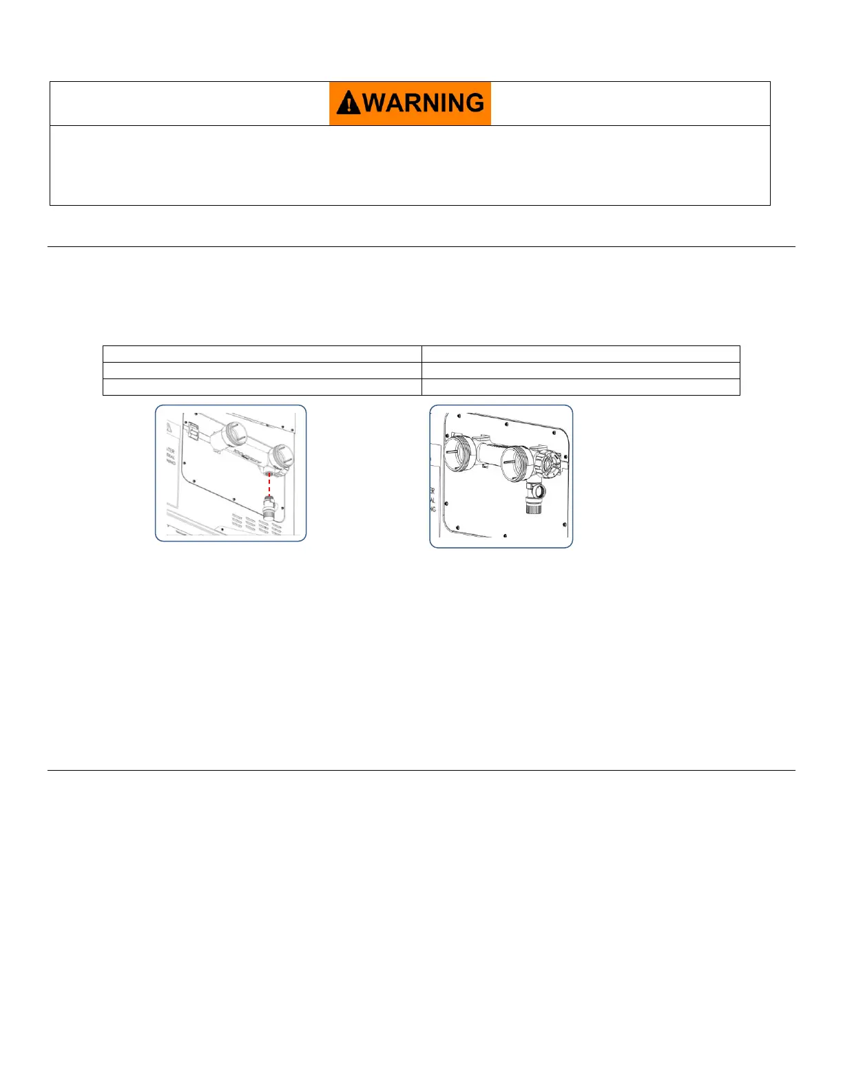
FITMENT OF PRESSURE RELIEF VALVE
A Pressure relief valve must be installed in accordance with local codes and installed vertically.
Have an authorised service technician replace the header 78660 with 78660PRV. Refer to page 25 of service instructions
“REPLACEMENT OF INLET/OUTLET HEADER”.
Locate Pressure Relief port at the outlet of the header. Fit a pressure relief valve complying with and having a total steam
discharge capacity, in BTUS/hr, not less than the value listed in the table below.
NORMAL HEATER OPERATION (LOGIC)
Ignition sequence
1. Heater is powered.
2. Heater is turned on.
3. 24Vac is sent from the controller to check water pressure switch is closed (for sufficient flow), and 104 °F (45 °C) and 131 F (55
°C) high limits are closed. (All safety controls must remain in a closed 24Vac circuit for heater to operate).
4. Thermostat calls for heat via the thermocouple in the inlet/outlet header.
5. If the temperature is under 40 °C and >1 degree below the set point the fan starts at a reduced ignition/firing rate.
6. The ignition module then looks to see the normally open air pressure switch has closed. It must register the switch closing to
prove that it wasn’t stuck in the closed position.
7. When it’s proven the fan is operating the fan will run at a reduced speed for a period of 30 seconds to purge the combustion
chamber of any unburnt gas.
 Loading...