EasyManua.ls Logo

Jandy AquaLink RS series - User Manual

Jandy AquaLink RS series
48 pages
Print Icon
To Next Page IconTo Next Page
Loading...
Troubleshooting Data
Troubleshooting Manual
WARNING
FOR YOUR SAFETY - This product must be installed and serviced by a pro fes sion al pool/
spa service technician. The procedures in this manual must be followed ex act ly. Failure to
follow warning notices and instructions may result in property damage, serious injury, or
death.
Pool/Spa Combination Systems
Pool/Spa Only Systems
Dual Equipment Systems
AquaLink
®
RS
All Button and
OneTouch
Control Systems
6919E

Other manuals for Jandy AquaLink RS series

Questions and Answers

  • M
    Melissa JacksonAug 17, 2025
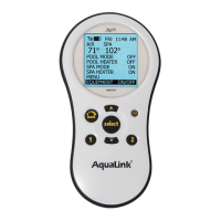
    What to do if my Jandy Control Panel system locked up?
    • S
      staylorAug 17, 2025
      If your Jandy Control Panel system has locked up, it may be due to a locked microprocessor. To resolve this, turn off the power to the system, disconnect the battery, and turn the power back on. Then, reconnect the battery and reset the time and date.
  • F
    Felicia RodriguezAug 20, 2025
    Why are my Jandy Control Panel programs not running at the correct time?
    • P
      Penny HughesAug 20, 2025
      If programs on your Jandy Control Panel are not running at the correct time, it's likely that the AquaLink system is displaying an incorrect time and date. To fix this, set the correct time and date on the control panel. Also, check the battery level in Diagnostics. If 'LOW BATTERY' is displayed, replace the battery to ensure the correct time and date are maintained.
  • R
    Randall PatelAug 22, 2025
    What to do if Jandy Control Panel is dead but override switches work?
    • A
      Andrew NguyenAug 22, 2025
      If the Power Center override switches operate in Service or Time Out Mode, but the Jandy Control Panel is dead (no lights or display), it indicates a power supply problem. Check the connection of the outside two wires (red & green) of the four-conductor cable. If wired correctly, check the voltage between these two wires. For an All Button system, the voltage should be 7+ VDC, and for a OneTouch system, 8+ VDC (use the higher voltage for a mixed system).
  • S
    simmonsbrittanyAug 25, 2025
    Why is my Jandy Control Panel showing all LEDs on but not communicating?
    • S
      shannonjohnsonAug 26, 2025
      If all LEDs are on at the Jandy Control Panel, and the part # and revision letter of the control panel software are displayed, but the control panel is not communicating with the power center PCB, check the two center wires (black & yellow) of the four-conductor cable. Also, check the installation of the PPD on the power center PCB. If the PPD is not seated correctly, the system will not communicate.
  • W
    Wendy MendozaAug 28, 2025
    How to fix Jandy Control Panel when pool cleaner runs without filter pump?
    • X
      xdavisAug 28, 2025
      If the pool cleaner booster pump turns on without the filter pump being on, and can run with the spa on in your Jandy Control Panel system, it indicates that the system isn't recognizing that DIP switch #1 is on. To resolve this, turn off all equipment buttons, then turn off the power to the system. Turn DIP switch #1 off, then on again. Finally, turn the power back on and test the system.
  • P
    pam32Aug 30, 2025
    Why some buttons on my Jandy Control Panel don't work?
    • T
      Todd WilkinsonAug 31, 2025
      If some buttons do not operate from the Jandy Control Panel or the power center override switches, it may be due to the wrong PPD chip installed at the power center PCB. Check the part number and revision letter by pressing the reset button at the control panel. The second part number and revision letter displayed is for the PPD indicating which model.
  • L
    Lisa BurtonSep 2, 2025
    What to do if all LEDs are on but override switches don't work on Jandy Control Panel?
    • A
      Amy BakerSep 2, 2025
      If all LEDs are on at the Jandy Control Panel and the part # and revision letter are displayed, but override switches at the power center do not operate, it could be due to: 1. A damaged or improperly installed PPD. 2. A damaged power center PCB. First, check the alignment of the PPD. If the PPD is installed correctly, replace the power center PCB.
  • B
    brian86Sep 5, 2025
    Why is my Jandy Control Panel RS system slow or display erratic?
    • D
      daniel57Sep 5, 2025
      If the RS System operation is slow or the display is erratic on your Jandy Control Panel, it's likely due to older firmware being installed. To resolve this, replace the socketed chip in the OneTouch printed circuit board with Firmware B11 or newer.
  • J
    Jessica NewtonSep 8, 2025
    Why does my Jandy Control Panel LCD screen stay on 'Firmware B11'?
    • D
      Danny YangSep 8, 2025
      If the LCD screen display stays on 'Firmware B11' (or later) on your Jandy Control Panel, there may be no communication between the indoor Control Panel and the Power Center J-box. Confirm that the DIP switch settings on both the Indoor Control Panel Transceiver and Power Center Transceiver are as follows: - DIPs 1-7 are set identically - DIP 8 is ON at the Power Center J-box PCB - DIP 8 is OFF at the Control Panel Transceiver PCB.
  • D
    Dustin ShahSep 12, 2025
    What to do if one button on Jandy Four Function Remote doesn't operate?
    • D
      dskinnerSep 12, 2025
      To address a non-operational button on the Four Function Remote or SpaLink RS of your Jandy system, replace the Four Function Remote or SpaLink RS. Use MENU, REVIEW, SPA SWITCH (or SPA LINK) to check programming.

Summary

Important Safety Instructions

General Safety Instructions and Warnings

Crucial safety information covering injury risks, hyperthermia, electrical hazards, and health precautions.

Control Panel Overview

Indoor Control Panel

Description of the indoor control panel's function and features for system operation.

Controller

Details on the controller's power supply, communication, and potential lock-up conditions.

Reset Switch

Explanation of the reset switch function for All Button and OneTouch controllers.

Controller

Diagnostics

Procedure to access and view the system's diagnostic information on the control panel.

Controller Troubleshooting

Troubleshooting steps for issues like the display not illuminating or communication problems.

Heater Operation

Explanation of heater operation indicators and troubleshooting steps for heating issues.

Power Center

Overview

Overview of the power center PCB, its role as the system's brain, and its components.

Power Center Troubleshooting

Troubleshooting guide for power loss issues related to the power center transformer.

Main Power Center PCB

Layout and description of the main power center PCB components and their functions.

Auxiliary Power Center

Overview

Explanation of the auxiliary power center's function and its relation to the main power center.

DIP Switches

Details on the function and settings of DIP switches on the power center bezel.

Water Temperature Sensor

Troubleshooting guide and resistance chart for the water temperature sensor.

3 HP Relay

Description of the 3 HP relay's operation, specifications, and wiring.

Two Speed Relay

Explanation of the two-speed relay's operation, specifications, and wiring for pump control.

Light Dimming Relay

Operation and wiring details for the light dimming relay and its control.

Jandy Valve Actuator

Operation

Detailed explanation of the Jandy Valve Actuator's internal wiring and operation principles.

Troubleshooting

Quick Check List

A quick reference table for common symptoms, problems, and possible solutions.

Controller Inoperable, Display Blank

Flowchart guide for diagnosing and resolving issues with an inoperable or blank controller display.

All Lights Lit on Controller

Troubleshooting flowchart for when all controller LEDs are lit but the unit is unresponsive.

Some Controller Buttons Do Not Operate

Guide for troubleshooting non-responsive controller buttons and checking firmware compatibility.

Three Amp Fuse Keeps Failing

Troubleshooting flowchart for persistent blowing of the three amp fuse on the power center PCB.

Heater Doesnt Fire

Flowchart for diagnosing why the heater is not firing or the heater LED is not on.

Flow Charts

OneTouch Menu Flow Chart

Visual representation of the OneTouch controller's menu navigation and options.

All Button Menu Flow Chart

Diagram illustrating the menu structure and navigation for the All Button controller.

All Button Cancel Flow Chart

Flowchart detailing how to cancel various functions and settings on the All Button controller.

Wiring Diagrams

AquaLink RS Pool;Spa Combination and Pool;Spa Only

Wiring diagrams for RS Power Center and PDA Power Center for Pool/Spa models.

AquaLink RS Dual Equipment

Wiring diagrams for AquaLink RS Dual Equipment models, including conversion wiring.

AquaLink RS Auxiliary Power Center

Wiring diagram for the AquaLink RS Auxiliary Power Center connections.

Power Center Bezel

Power Center Bezel Options

Illustrations and part numbers for different Power Center Bezel configurations.

Limited Warranty Information

Jandy AquaLink RS series Specifications

General IconGeneral
WeatherproofYes
AutomationYes
ExpandabilityYes
Smartphone ControlYes
Power Source120V AC
CommunicationRS-485
Humidity Range0% to 95% non-condensing
Maximum Load CapacityVaries by model
DimensionsVaries by model
WeightVaries by model
Compatible DevicesJandy pumps, filters, heaters, lights, valves
Wireless ControlOptional (with iAquaLink)

Related product manuals