Page 23
5.4 3 HP Relay
5.4.1 Operation
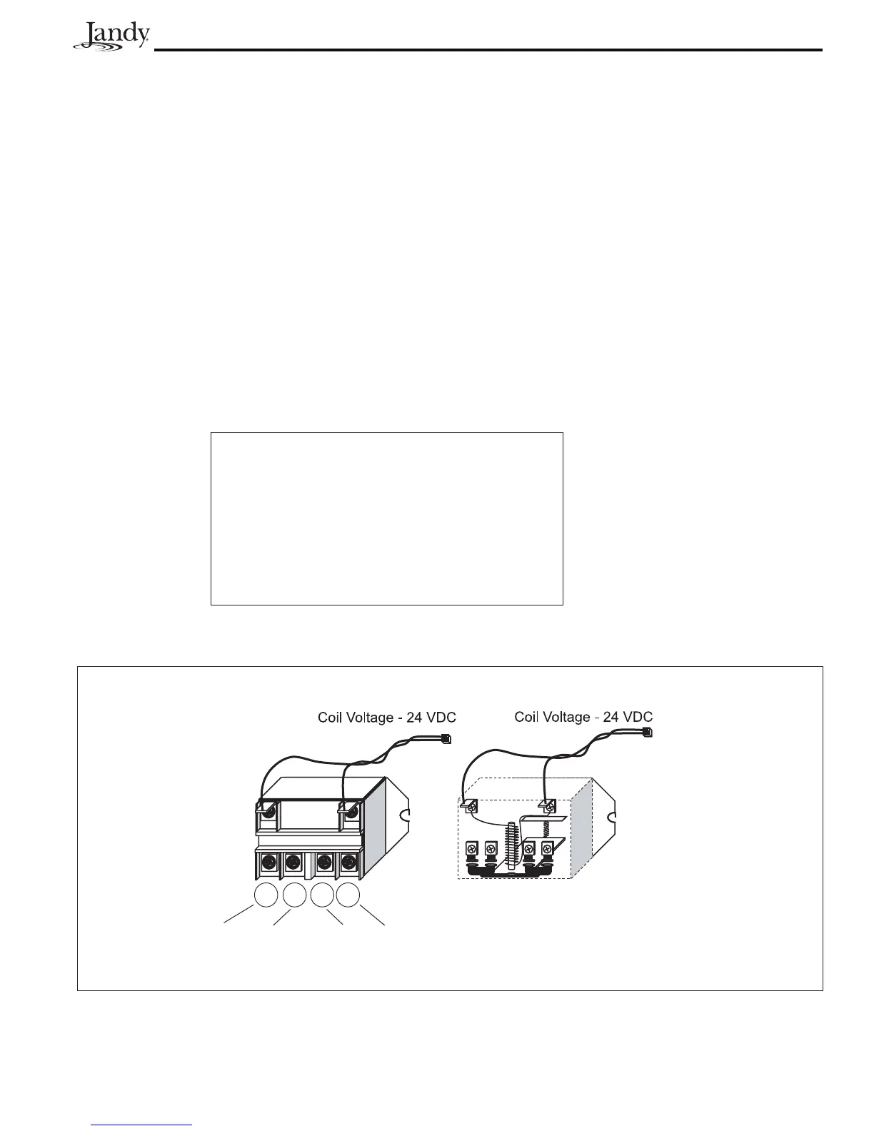
1. A standard 3 HP Relay's coil is supplied with 24 VDC from the power center PCB via one (1) of the driver chips.
When 24 VDC is received by the relay's coil wires, it closes the contacts that complete the circuit to turn on the
equipment (i.e., power supplied to Line 1 goes out Load 1 to the equipment). See Figure 16.
2. Standard 3 HP Relays may be wired to activate a 120 VAC circuit (i.e. Line 1/Load 1) or a 240 VAC circuit (i.e.
Line 1/Load 1 and Line 2/Load 2).
Note If a relay's coil wires are shortened, or an AC relay coil is plugged into a relay socket, when that circuit is activated, it will
damage one of the relay driver chips on the power center PCB.
Specifi cations
Maximum Contact Ratings:
3 HP at 240 VAC
1 1/2 HP at 120 VAC
1500 watts (per contact) - Incandescent
Relay coil - 24 VDC
Resistance across coil - 300 Ohms
Amperage draw of coil - 0.10 Amps
Figure 16. 3 HP Relay
2 4 6 8
Line 1 Load 1 Line 2 Load 2
 Loading...