Page 17
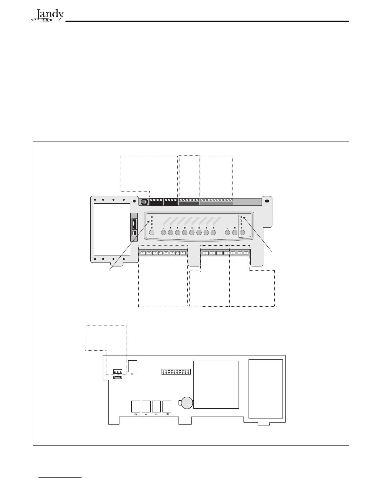
4.3.2 PCB Voltages
1. From Power Center to Controller, between terminals one (1) and four (4) of the two (2) red terminal blocks = 8 to
10 VDC.
2. To JVA 2444 = 24 to 28 VAC*.
3. To Relay Coils = 24 to 32 VDC*.
4. Transformer Primary = 105 to 130 VAC.
5. Transformer Secondary = 24 to 28 VAC.
* Never measure voltage at the socket.
S1
S2
654321
10987654321
4321
4321
RESET
SERVICE
TIME OUT
FILTER PUMP
AUX
1
AUX
2
A
UX
3
AUX
4
AUX 5
AUX 6
AUX 7
RS6 & RS8 ONLY
RS8 ONLY
HEATER
SOLAR
POOL MODE
SPA MODE
SPA DRAIN
SPA FILL
AUTO
Connection to
Controller
10 VDC
Spa
Side
Switch
Sensors
and
Heater
Relay Sockets
24 VDC
Relay Sockets
24 VDC
JVA Sockets
24 VAC
Filter Pump
Aux 1
Aux 3
Aux 2
Aux 4
Aux 5
Aux 6
Aux 7
Intake
Return
Cleaner
Solar
Solar Pump
Elect. Htr.
Spare
Auto Light
Valves Light
Transformer
Connection
24 VAC
Figure 12. PCB Voltages
 Loading...