Page 41
Section 9. Wiring Diagrams
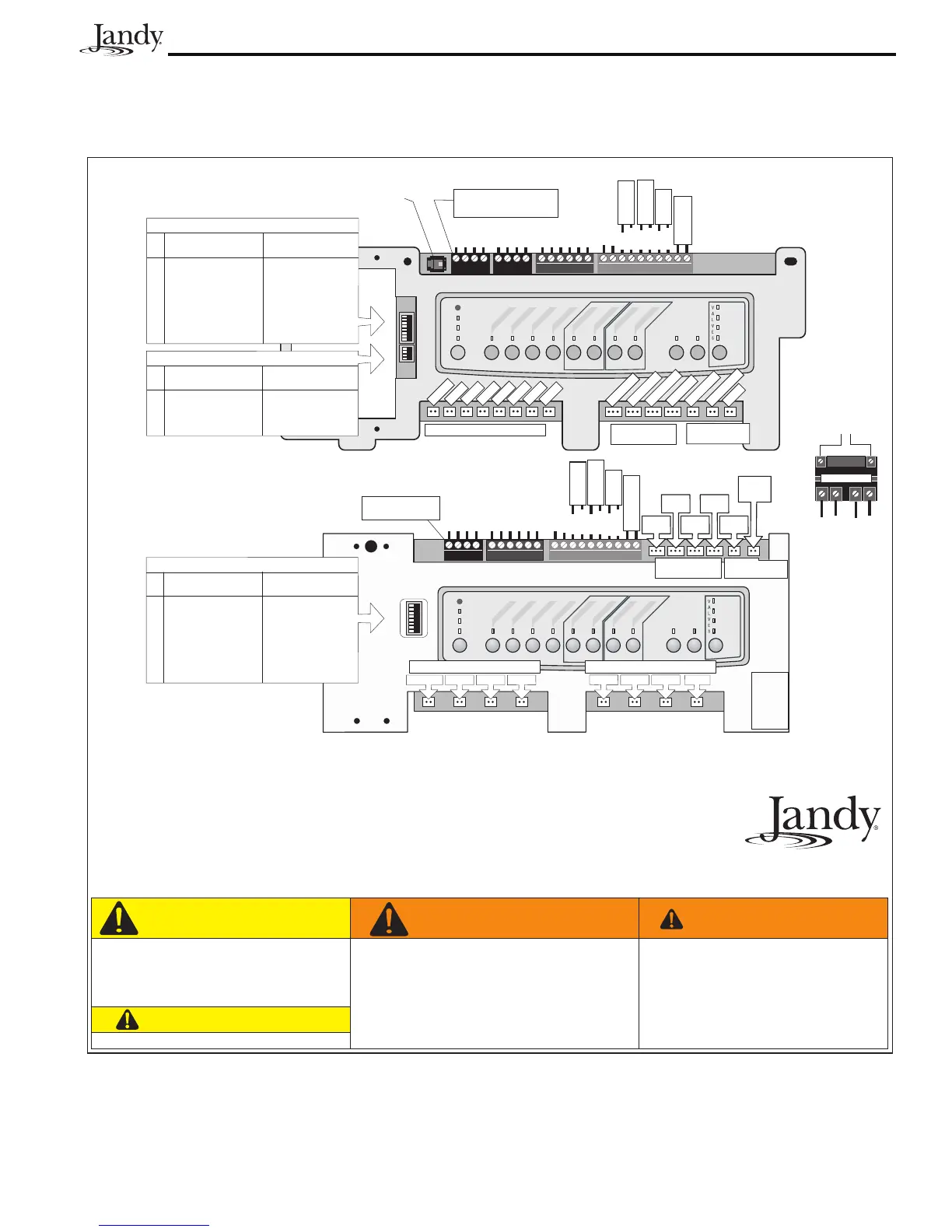
9.1 AquaLink RS Pool/Spa Combination and Pool/Spa Only
Sheet #7192, Rev. H
6000 Condor Drive • Moorpark, CA USA 930201
707.776.8200 • Fax 707.763.7785
Litho in USA © Jandy Pool Products, Inc. 0703
IMPORTANT INSTALLATION INSTRUCTIONS:
Enclosure: Rainproof (Type 3R, IPX3) suitable for swimming pool/spa applications.
1. Installation must be by a qualified electrician and must comply with all national, state, and local codes.
2. Power Center must be mounted at least five (5) feet away from the inside edge of the pool.
Canadian installations must be at least three (3) meters from the water.
Les installation Canadiennes dolvent se trouver à au moins trois (3) mètres de l’eau.
3. Install to provide drainage of compartments for electrical components.
4. After wiring, install panels over wiring compartments and keep Power Center door closed.
5. For technical information, call Jandy Pool Products, Inc. at 707-776-8200 ext. 260.
To reduce the risk of injury, do not permit
children to use this product unless they
are closely supervised at all times. Water
temperature in excess of 100°F/38°C
may be injurious to your health.
WARNING
AVERTISSEMENT
Pour réduire le risque de blessures, ne
pas permettre aux enfants d’utiliser ce
produit à moins qu’ils soient supervisés
de près en tout temps. Des températures
de l’eau supérieures à 38°C/100°F peu-
vent présenter un danger pour la santé.
CAUTION
Lire la notice technique.
ATTENTION
Read Installation Manual completely
before installing. This product must
be wired in accordance with the
Installation Manual.
Freeze/
Air Senso
r
Water Temp.
Sensor
Intake
JVA
Cleaner
JVA
Solar
Pump
Return
JVA
Solar
JVA
Elect.
Heater
Red
Black
Green
White
Yellow
Green
Black
Red
Brown
To Remote
(brown terminal bar)
To Sensors, etc.
(green terminal bar)
To Controller
(red terminal bar)
4321 654321
10987654321
Blue
Red
Black
Red
Black
Solar
Sensor
Low
V
oltage
Heater
F. Pump
Aux. 1 Aux. 2 Aux. 3
Aux. 7
Aux. 6Aux. 5Aux. 4
Relay Sockets
(24 VDC output)
JVA Sockets
(24 VAC output)
Battery
(9Volt)
Red
Black
Not Used
Not Used
RESET
SERVICE
TIME OUT
FILTER PUMP
A
UX
1
AUX 2
A
UX
3
AUX 4
AUX 5
A
UX
6
A
UX
7
RS6 & RS8 ONLY
RS8 ONLY
HEATER
SOLAR
POOL MODE
SPA MODE
SPA DRAIN
SPA FILL
Relay Sockets (24 VDC output) Relay Sockets (24 VDC output)
AUTO
For Optional Multiplex PCB
Connect red four-pin connector
to Multiplex Board
PDA Power Center Wiring Diagram
RS Power Center Wiring Diagram for Pool and Spa and Only Models
Freeze/
Air Sensor
Water Temp.
Sensor
Red
Black
Red
Black
Solar
Sensor
Red
Black
S1
S2
RESET
SERVICE
TIME OUT
FILTER PUM
P
AUX
1
A
UX
2
AUX
3
AUX
4
AUX 5
AUX 6
AUX
7
RS6 & RS8 ONLY
RS8 ONLY
HEATER
SOLAR
POOL MODE
SPA MODE
SPA DRAIN
SPA FILL
AUTO
654321
10 9 8 7 6 5 4 3 2 1
4321
4321
Red
Black
Green
White
Brown
Blue
Low Voltage
Heater
Not
Used
Not
Used
Green
Black
Red
Yellow
Green
Black
Red
Yellow
To Sensors, etc.
(green terminal bar)
To Remote
(brown terminal bar)
To Controller
(red terminal bar)
F. Pump
Aux. 1
Aux. 2
Aux. 3
Relay Sockets (24 VDC output)
Aux. 4
Aux. 5
Aux. 6
Aux. 7
Cleaner J
V
A
Solar Pump
Relay Sockets
(24 VDC output)
JVA Sockets
(24 VAC output)
Intake JVA
Return J
VA
Solar J
V
A
Elect. Heater
Spare
Connect red four-pin connector
to Multiplex Board
Service Controller Connector
For Optional Multiplex PCB
DIP SWITCH SETTINGS
Factory Setting
OFF
Aux1
1 SPD Filter Pump
Aux 3
Cool Down
Normal
Spare Aux (Pool Mode)
See Manual
Gas Heater
#
1
2
3
4
5
6
7
8
When Turned
ON
Cleaner
2 SPD Filter Pump
Spa Spillover
Disabled
See Manual
Spare Aux (Spa Mode)
See Manual
Heat Pump
S1 DIP SWITCH SETTINGS
Factory Setting
OFF
Aux1
1 SPD Filter Pump
Aux 3
Cool Down
Normal
Spare Aux (Pool Mode)
See Manual
Gas Heater
#
1
2
3
4
5
6
7
8
When Turned
ON
Cleaner
2 SPD Filter Pump
Spa Spillover
Disabled
See Manual
Spare Aux (Spa Mode)
See Manual
Heat Pump
S2 DIP SWITCH SETTINGS
Factory Setting
OFF
Solar Heat Priority
Not Used
Not Used
Not Used
#
1
2
3
4
When Turned
ON
Heat Pump Priority
Not Used
Not Used
Not Used
Line One
Line Two
Load One
Load Two
RELAY
Relay Socket

 Loading...

