Page 24
Jandy
®
JXi
™
Gas-Fired Pool and Spa Heater | Installation & Operation Manual
4.0
5.0
6.0
7.0
8.0
9.0
8.0
10.0
12.0
14.0
16.0
18.0
20.0
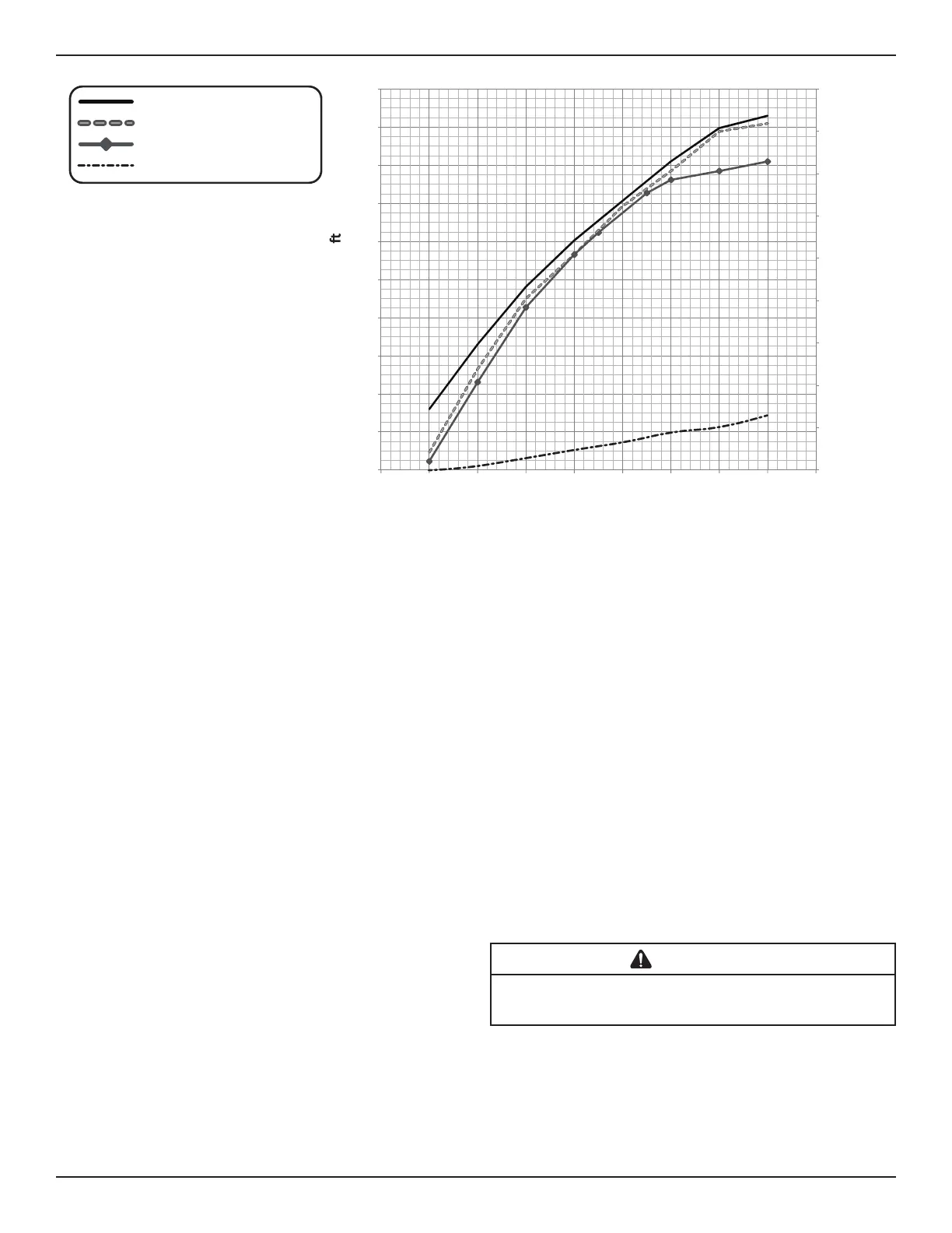
JXi 200K BTU Heater
JXi 260K BTU Heater
JXi 400K BTU Heater
0.0
1.0
2.0
3.0
0.0
2.0
4.0
6.0
20 30 40 50 60 70 80 90 100 110
ign Pressure Drop (psi)De
esign Head Loss
( Head)
D
JXi VersaFlo™ Bypass
Figure 10. Head Loss Chart
For ASME heater models JXi400NC, JXi400PC, JXi260NC and JXi260PC please go to “Appendix A. ASME
®
Header” on page 55.
• Adjust the valve to bring the flow rate within the
acceptable range. See Table 4.
• Remove the valve handle to avoid tampering.
5.1.1 Manual Bypass Valve
A manual bypass valve is to be installed in any
system in which the pump flow exceeds 100 gpm to
the heater.
• Connect a valve between the water inlet and
outlet. See inset “a.” in Figure 9.
5.1.2 Pump Sizing for New Pool Construction
When sizing a pump for the system, the head loss
for all system components must be added together
when determining the design flow rate. Component
“Head Loss at Flow” curves are available from
equipment manufacturers.
NOTE: In order to properly establish head loss at flow for
a filter, remember that a “dirty” filter can typically
add 10 psi of additional head loss (23 extra feet
of head). This must be considered when sizing a
pump for a new pool system.
5.1.3 Pump Sizing for Replacement in an
Existing Pool
If the JXi heater replaces a different model of
heater, determine if the existing pump is capable
of providing the minimum flow of 30 gpm. JXi
heaters are high efficiency heaters. Heaters typical
of this construction may have higher head loss
characteristics than the one being replaced.
CAUTION
Heater failure due to insufficient water flow is not covered under
warranty. See measurements in the Head Loss Chart. See Figure 10.
5.2 Plumbing Connections
The heater has a standard 2 inch water manifold and
coupling design. With this feature, only nominal two
inch PVC or CPVC may be connected to the heater.
However, by installing appropriate pipe adapters
and two-inch pipe (supplied by the installer), any size
existing pipe may be fitted to the heater.