Page 31
Jandy
®
JXi
™
Gas-Fired Pool and Spa Heater | Installation & Operation Manual
Wiring connections must be made exactly as shown
in the wiring diagram found on the inside of the
heater door. The NEC and CEC also require that
the equipment and/or appliances associated with
the pool water circulating system, including, but not
limited to, pump motors and heaters, be bonded
together as part of the equipotential bonding grid.
Zodiac Pool Systems LLC provides a special labeled
bonding lug on the manifold side of the heater to
accommodate this requirement.
All electrical connections and wiring must be done
by a certifi ed electrician only. Electrical wiring must
also be in accordance with the latest edition of the
National Electrical Code
®
(NEC
®
), ANSI
®
/National
Fire Protection Association
®
(NFPA
®
) 70, or in
Canada, the Canadian Electrical Code (CSA
®
C22.1)
unless local code requirements indicate otherwise.
The heater comes factory-wired for installation with
240 Volt, 60 Hz AC fi eld electrical supply. If the
use of 120 Volt, 60 Hz AC fi eld electrical supply is
required, You must fi rst change the position of the
voltage selector board on the power distribution
board. See Section 6.3 for details
WARNING
ELECTRICAL SHOCK HAZARD. This heater contains wiring that
carries high voltage. Contact with these wires may result in severe
injury or death.
CAUTION
Label all wires prior to disconnection when servicing controls. Wiring
errors can cause improper and dangerous operation.
Verify proper operation after servicing.
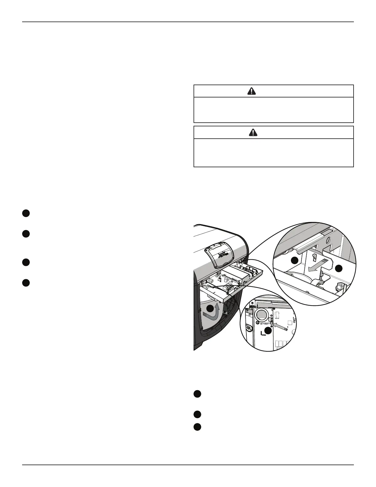
6.1 Service Access
• Remove the four screws holding the front heater
panel in place to expose the raceway.
Locate the raceway lock release on the interior of
the heater raceway.
b
Using a screwdriver or comparable tool; press
into the raceway release orifi ce until the raceway
latch releases, and the raceway swings free.
Secure the raceway in place by lifting until the
locking latch engages.
d
Push the tab on the locking latch to the
left to release.
• Press raceway down and back until an audible
click indicates that it is latched in position.
• Replace heater front panel.
Tech Tip: For greater access remove the top panel
by removing the 4 black screws on the outside of the
heater.
NOTE: Before the raceway can be rotated for the fi rst
time a shipping zip tie must be cut. This zip tie is
threaded at the raceway release point see item (a).
While cutting this zip tie be sure not to damage or
abrade any of the wires.
d
b
c
a
H0495500_REVA
6.2 Main Wiring Connections
The main wiring connections should be available
externally to the heater at the time it is unpacked.
Use fl exible conduit to run the main power lines from
the power source to the heater connections. No
external junction box is required.
• Ensure that all electrical power is shut off to the
heater at the breaker.
• Ensure that the fi lter pump is off and will stay off
for the remainder of the procedure.
• Follow applicable service access instructions
from Section 6.1.
Run conduit and power lines from main power
source to the heater side panel.
b
Make wire connections via wire nuts.
Push wire connections through the knockout into
the heater body. Be careful not to damage or abrade
any wiring during this procedure.