Page 35
Jandy
®
JXi
™
Gas-Fired Pool and Spa Heater | Installation & Operation Manual
7.2.1 Install the Remote TSTAT
• Turn off the power to both the pool/spa control
system and the heater unit.
• Follow service access instructions from
Section 6.1.
• Run the wires from the pool/spa control system
through the low voltage knockout on the right or
left hand side of the heater.
• Connect the wiring from the pool/spa control
system to the heater remote control terminal.
• Connect the two wires to Pool and Common (not
Spa) on the J6 terminal bar. See Figure 15 item
“b”.
• Reinstall panel.
• Restore power to the heater and the pool/spa
control system.
NOTE: If you install a time clock to control the filter pump
operation, it is recommended that the time clock
have its own low voltage (Fireman’s) switch to
turn off the heater before turning off the pump.
The switch should shut off the heater about 15
minutes before the filter pump shuts off. This will
allow for a more efficient operation by removing
any residual heat contained in the heat exchanger
back to the pool.
CAUTION
To avoid damage to the heater, do not connect the power supply of
the heater to the output side of the clock if your time clock simply
interrupts the high voltage power supply or has a high voltage output.
Doing so will prevent the blower from purging the residual heat from
the heater when the heater turns off. The blower must be allowed to
run for 45 seconds after the heater shuts off.
7.2.2 Configure the Control Panel
• Make sure the pool heater is OFF.
• Press and hold MENU, then the POOL and SPA
buttons for 5 seconds to access Service Setup
mode.
NOTE: The display will revert back to OFF 1 minute after
the last key press.
• Press MENU, REMOTE OFF (default) is displayed.
• Use Up or Down to scroll through the Remote
options until REMOTE TSTAT is displayed, then
press MENU to select.
• Press POOL or SPA to exit Service Setup mode.
• Press POOL or SPA to adjust the set point to the
maximum 104°F (40°C).
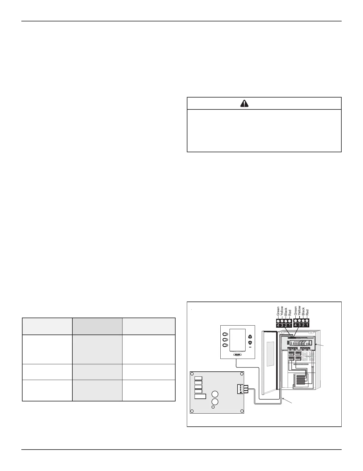
7.3 “Smart” Communication via RS-485
To provide “smart” communication between the JXi
and a power center board (PCB) (AquaLink
®
Infinity,
AquaLink RS, AquaLink PDA, and AquaLink Z4)
through a red four-pin RS485 connector, your PCB
must have the appropriate firmware. To determine
the REV of the AquaLink RS PCB firmware in your
system, refer to Table 6. All AquaLink Infinity Firware
revisions are RS485 ready.
7.3.1 PCB and Firmware Identification for
AquaLink RS and AquaLink PDA Connections
COMPONENTS
REV MMM
or EARLIER
Rev n
or LATER
RS485
Connectors
One set of
four
Two sets of
four
JVA Sockets
24 VAC
Located on top of
board
Located on bottom of
board
Relay Sockets
24 VDC
10 total sockets. Eight
located on bottom, two
on top of board
11 total sockets.
All located on
bottom of board.
Table 6. AquaLink RS Power Center Board
Identification Features
RESET
SERVICE
TIME OUT
FILTER PUMP
AUX 1
AUX 2
AUX 3
AUX 4
AUX 5
AUX 6
AUX 7
RS6 & RS8 ONLY
RS8 ONLY
HEATER
SOLAR
POOL MODE
SPA MODE
SPA DRAIN
SPA FILL
AUTO
654321
10 9876 54321
4321
4321
To Sensors, etc.
(green terminal bar)
To Remote
(brown terminal bar)
To Controller
(red terminal bar)
GR Y BK R
4 3 2 1
Power Center
Indoor Controller
JXi Control
AquaLink RS System Shown for Reference
RS Control
System
Power
Center
Bezel
22 Gauge
4 Conductor
Wire
Figure 17. Wiring the JXi to a Zodiac
®
Remote