Page 36
Jandy
®
JXi
™
Gas-Fired Pool and Spa Heater | Installation & Operation Manual
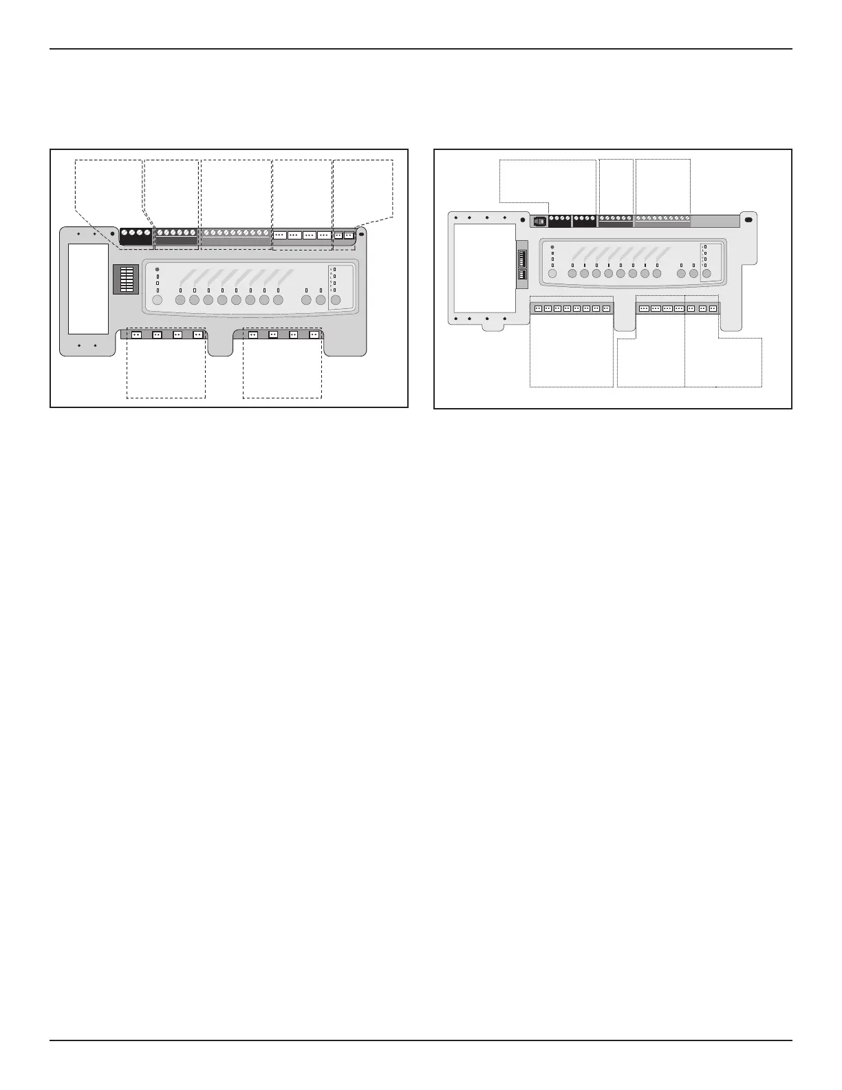
If your PCB firmware is REV MMM or earlier:
Connect via a 2-wire connection. See Section 7.2
for details.
Spa Side
Switch
Sensors and
Heater
JVA Sockets
24 VAC
Relay Sockets
24 VDC
Connection to
Controller:
RS485
Connectors
Relay Sockets
24 VDC
Relay Sockets
24 VDC
Intake
Return
Cleaner
Solar
Solar Pump
Elect Htr
Filter Pump
Aux 1
Aux 2
Aux 3
Aux 4
Aux 5
Aux 6
Aux 7
4321
654321
10 9876 54321
RESET
SERVICE
TIME OUT
FILTER PUMP
AUX 1
AUX 2
AUX 3
AUX 4
AUX 5
AUX 6
AUX 7
RS6 & RS8 ONLY
RS8 ONLY
HEATER
SOLAR
POOL MODE
SPA MODE
SPA DRAIN
SPA FILL
AUTO
Figure 18. AquaLink RS PCB with Firmware Rev MMM
or Lower
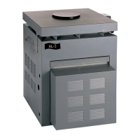
If your PCB firmware is REV N or higher:
Connect via RS485 connection. See Section 7.3.2
for details.
S1
S2
654321
10 9876 54321
4321
4321
RESET
SERVICE
TIME OUT
FILTER PUMP
AUX 1
AUX 2
AUX 3
AUX 4
AUX 5
AUX 6
AUX 7
RS6 & RS8 ONLY
RS8 ONLY
HEATER
SOLAR
POOL MODE
SPA MODE
SPA DRAIN
SPA FILL
AUTO
Connection to
Controller:
RS485 Connectors
Spa
Side
Switch
Sensors
and
Heater
Relay Sockets
24 VDC
Relay Sockets
24 VDC
JVA Sockets
24 VAC
Filter Pump
Aux 1
Aux 3
Aux 2
Aux 4
Aux 5
Aux 6
Aux 7
Intake
Return
Cleaner
Solar
Solar Pump
Elect. Htr.
Spare
Figure 19. AquaLink RS PCB with Firmware Rev N or
Higher
7.3.2 RS-485 Connection Procedure
• Turn off the power to both the heater and the
controller.
• Open the power center enclosure and remove the
low voltage dead front.
• Use 22 gauge 4-conductor wire to run between
the heater and the control system and match the
wire color order. See Figure 16.
• The wires coming from the heater can be
“doubled up” on the red RS485 terminal bar with
the four wires from the indoor controller.
• Check all wiring, then apply power to both the
heater and the control system. Verify operation in
either Service or Auto mode. Refer to your Control
System manual for operating instructions.
When the heater is connected to an external
controller, all functionality of the heater control
panel is disabled, therefore heater functions can be
controlled only from the controller. Control can be
restored to the local heater control panel by either
disconnecting the red RS485 terminal or by entering
the service setup mode selecting REMOTE then
STANDALONE. Control can be sent back to the
external controller by re-entering the service setup
mode and selecting JANDY RS485, unplugging and
replugging the RS485, or by cycling power to the
heater with the RS485 connected.
Do not connect more than two (2) wires to any of the
terminals in the Control System when connecting
peripheral devices. If connecting the heater to the
control system creates this situation, then a Multiplex
PCB Kit, which includes the Multiplex Board (part #
6584) must be used. Call Jandy Technical Support at
800.822.7933 with any questions.
NOTE: Only an AquaLink® RS System with firmware
revision “N”, or higher, will support the heater
interface. Refer to Table 6 along with Figure
18 and Figure 19 to determine the REV of
your system’s firmware. If it is “N” or higher,
continue with these procedures. If it is MMM or
lower, follow the procedures in Section 7.2 for
connecting to a remote TSTAT.
NOTE: Only a PDA System with firmware revision 4.1, or
higher, will support the heater interface.