Page 30
Jandy
®
JXi
™
Gas-Fired Pool and Spa Heater | Installation & Operation Manual
5.6 Auxiliary Components, Chlorinators,
Ozone Generators and Sanitizing
Chemicals
The JXi heater is manufactured with materials
that are not compatible with high concentrations
of ozone, chlorine, bromine, or other sanitizing
chemicals. Heater damage caused by improper
water chemistry or plumbing configurations are not
covered by the Zodiac Pool Systems LLC warranty.
All questions should be directed to technical support
at 800.822.7933. Additional information can be
found at www.jandy.com. Be sure to adhere to the
following:
• All sanitation equipment, including chemical
feeders and ozone generators, will need to be
installed as the last piece of equipment in the pool
circulation system.
• A chemically resistant check valve will also need
to be installed between the sanitation equipment
and the heater to prevent back-flow of high
concentration of sanitizer from entering the heater.
• Wire any electrical sanitation equipment so that it
cannot operate unless the filter pump is running.
• Always follow pool chemical manufacturer’s
instructions when adding chemicals to pool.
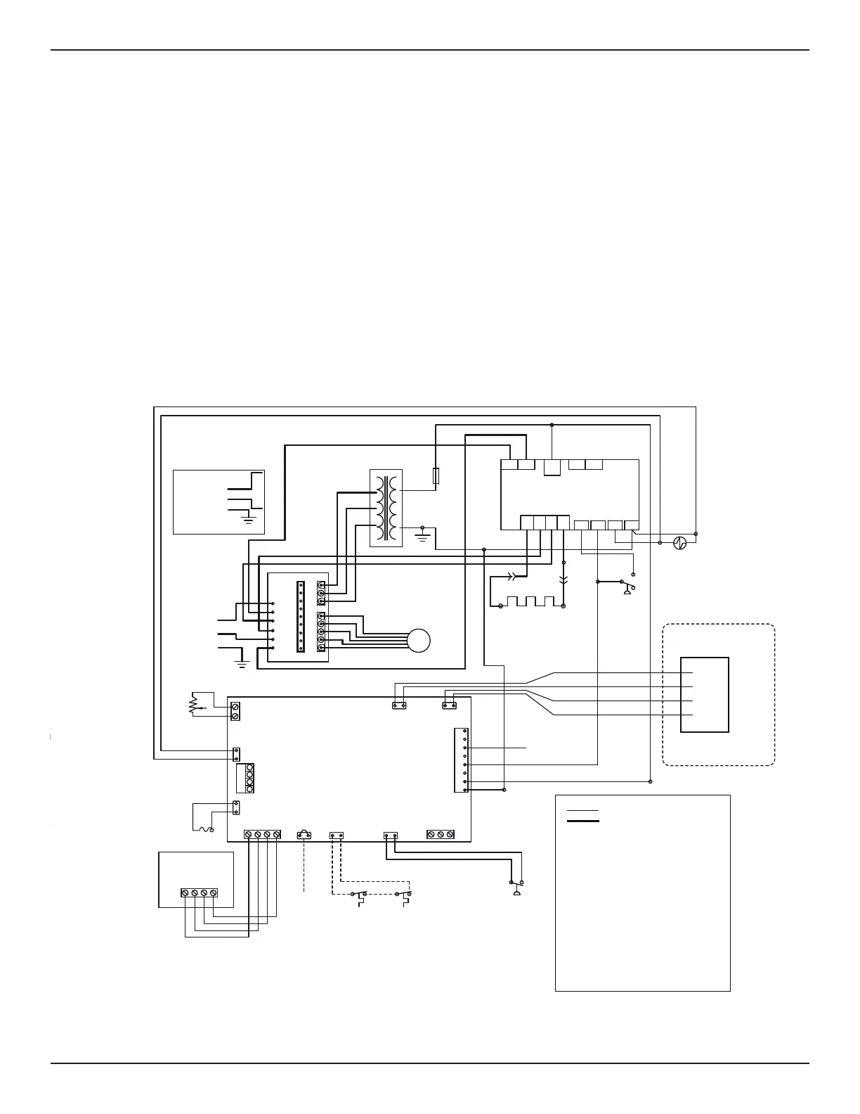
Section 6. Electrical Connections
Part Number: H0402900 REV A (wiring diag) ; H0416500 REV A (note)
Description: JXi Heater - Wiring Diagram Label for inside front panel
Size: H0402900 REV A: 6.25 x 7 inches ; h0416500 REV A: 2.5 x 2.75
Color: Black
L1
F1
ACN1
ACH1
L2
F2
G
R
BK
BLOWER
MOTOR
BK
R
Y
BL
W
IGNITION CONTROL
F1
F2
24
VAC
FV+
FV-
IGN
120
L1 L2
IGN
FS
W
GNDVAL
BK
W
BK
BL
R
GY BK
24 VAC
R
Y
HOT SURFACE
IGNITER
W
GY
W
TRANSFORMER
WATER
AquaLink RS
TEMP
GAS
VALVE
USER
INTERFACE1
BK O BL
R
HIPRESS/
HILIMIT
WATER
PRESS
REMOTE
SPA POOL COM
REV
VALVE
24VAC
PUMP
COMP/
IGN
FAN/
LOUVER
UNIVERSAL
CONTROLLER
POWER INTERFACE
UNIVERSAL
CONTROLLER
USER INTERFACE
POWER
INTERFACE
BK O BL R
AIR FLOW
SWITCH
GAS VALVE
WATER
TEMP
SENSOR
BL
W
BK
TO PUMP RELAY
CONTACTS (IF USED)
W
FUSE
R
Y
O
O
Y/BK
O
BR Y
BR Y
R
BL
BK
BK
BK
W
BK
BL
BR
Y
W W
W
VGY
BK
BK
PSW
Y/BK
C
NO
NC
Y/BK
COIL/AIR
TEMP
J3 CONNECTOR
Factory Wired 24V
Factory Wired 120V/240V
BK - BLACK
BL - BLUE
B/BK - BLUE WITH BLACK TRACE
G/BK - GREEN WITH BLACK TRACE
PK - PINK
BR - BROWN
G - GREEN
GY - GRAY
O - ORANGE
R - RED
V - VIOLET
W - WHITE
Y - YELLOW
Y/BK - YELLOW WITH BLACK TRACE
120 VAC
HEATER
POWER
SUPPLY
Alternate 120V Wiring*
G
R
BK
NEUTRAL
HOT
Voltage Selector Card Must Be Rotated.
LIMIT
SWITCH
57˚C
(135˚F)
LIMIT
SWITCH
66˚C
(150˚F)
WATER
PRESS
SWITCH
NOTE: SI L’UN QUELQONQUE DES FILS
D’ORIGINE FOUMIS AVEC LE
CHAUFFE-PISCINE DOIT ÊTRE REMPLACÉ,
UN FIL POUR APPAREILS ÉLECTRIQUES À
TOLERANCE NOMINALE DE 105°C DOIT
ÊTRE EMPLOYÉ. SI LE FIL PORTE LE
SYMBOLE ---------, LE REMPLACER
UNIQUEMENT PAR UN FIL POUR
APPAREILS ÉLECTRIQUES À TOLERANCE
NOMINALE DE 200°C.
NOTE: IF ANY OF THE ORIGINAL WIRE AS
SUPPLIED WITH THE HEATER MUST BE
REPLACED, APPLIANCE WIRING MATERIAL
RATED FOR 105°C MUST BE USED. WHERE
MARKED THUS - - - - - , APPLIANCE WIRING
MATERIAL RATED FOR 200°C MUST BE USED.
H0416500 Rev B
die line, does not print
2.5 x 2.75
Accessory
Leads
Optional
VersaFlo™ Bypass Accessory
FL
TEMP
FOR AIR
LOUVER
STARTER
(IF USED)
G/BK
B/BK
PK
PK
VENT
TEMPERATURE
LIMIT
240°C
(464°F)
BYPASS
MOTOR
BYPASS
SWITCH
W
W
(a)
(b)
(c)
(d)
(e)
(f)
(g)
(h)
(i)
(j)
(k)
(l)
Figure 15. JXi Connections / Schematic Wiring Daigram