Page 29
Jandy
®
JXi
™
Gas-Fired Pool and Spa Heater | Installation & Operation Manual
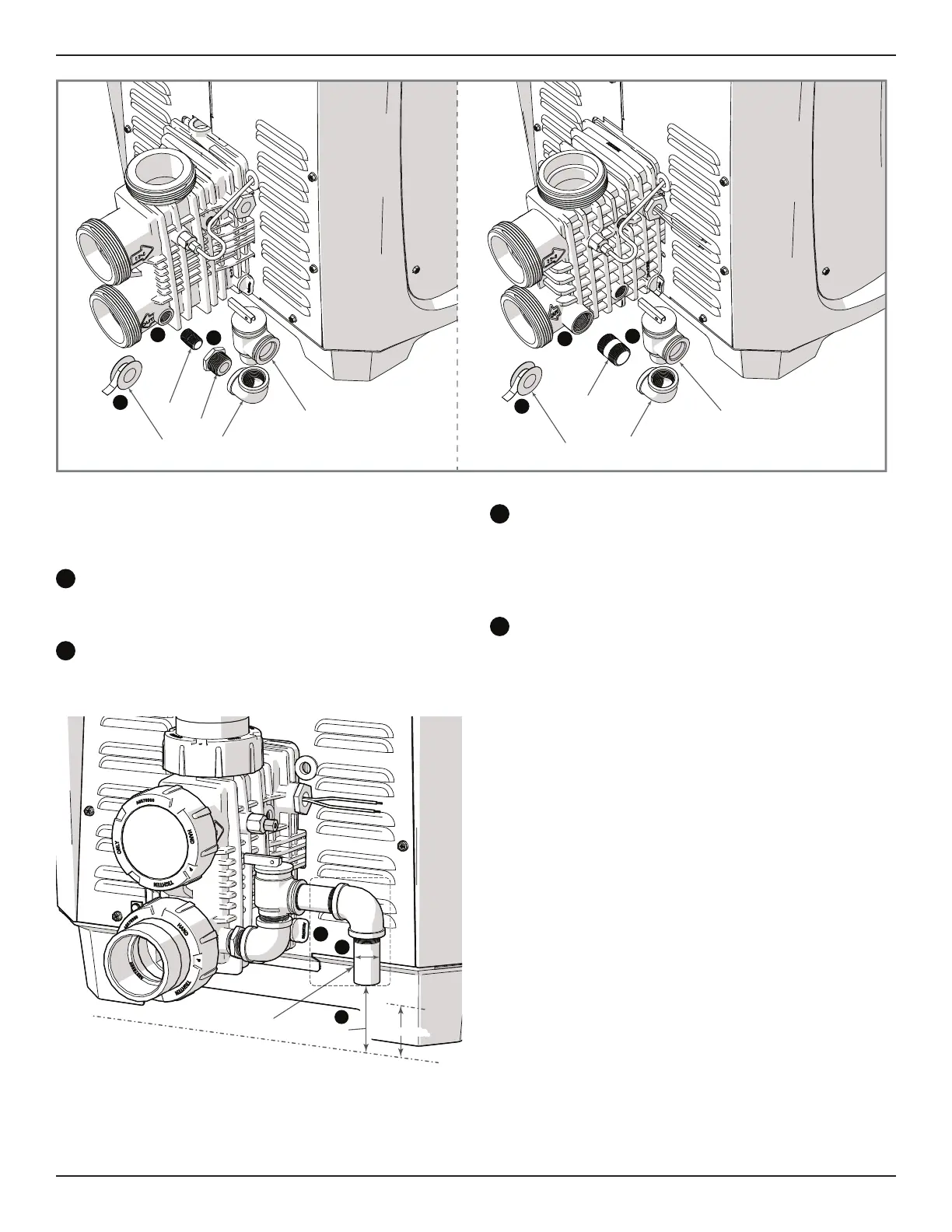
For header type B: Assemble the 3/4 in threaded
nipple, elbow and pressure relief valve. Make sure to
get a sung fi t. Do not overtighten.
Install the pressure relief valve assembly at the
heater header. Make sure to get a sung fi t. Do not
overtighten.
The fi nal orientation of the pressure relief valve
should be vertically aligned with the discharge
opening facing away from the heater header.
g
h
i
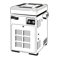
Header Type A Shown
Threadless Discharge Pipe
Ground Level
6 in (152 mm) Max
2 X (Øa) Min.
Øa
*
*Not supplied by Zodiac
NOTE: Hardware showing in dotted line is not provided
by Zodiac. Pressure Relief Valve hardware is
provided on ASME heater models only.
h
Install a discharge pipe from the pressure relief
valve discharge opening to a safe area. This is a
precaution to prevent the possibility of personal
injury or property damage in the event scalding
water is discharged from the pressure relief valve.
Install the discharge pipe so that there is no
trapped or standing water in the piping. Discharge
piping must be facing down, terminating with a
threadless nipple, no more than 6 in (152 mm) and
no less than twice the diameter of the discharge pipe
from the fl oor or drain/receptor.
• Discharge piping must be open with no reducers
or shut-off valves or other restrictions.
• Discharge piping must be positioned so that any
discharged water will have an appropriate drain or
run-off path away from the heater and other pool
equipment.
• To ensure the continued proper operation of
the pressure relief valve, the valve should be
tested once a year. To test, lift the lever with the
circulation system running to ensure that water
will pass through. When the lever is down, there
should be no leaks from the outlet.
e
e
f
f
d
d
3
1
6
6
2
1
4
55
Header Type “A” Header Type “B”