Page 28
Jandy
®
JXi
™
Gas-Fired Pool and Spa Heater | Installation & Operation Manual
5.5.1 Install Pressure Relief Valve Kit R0336101
For ASME heater models JXi400NC, JXi400PC, JXi260NC and JXi260PC please go to “Appendix A. ASME
®
Header” on page 55.
• Turn off the electrical power to the heater.
• Turn off the main gas supply to the heater.
• If the heater has been operating, ensure you
allow enough time for remaining water in the heat
exchanger to cool down before beginning. It is
recommended that protective gloves be worn
during the entire procedure.
• Make sure the fi lter pump is off and will remain off
for the duration of the installation procedure.
• If the heater is below the surface level of the
water in the pool or spa, close all shut-off valves
between the heater and the pool.
CAUTION
Use PTFE (Tefl on) tape only on the threads of the pipe nipple
attachment to the plastic header. Do not use pipe compound or pipe
dope on threads or any part that comes into contact with the plastic
header. These compounds may damage the header over a period of
time.
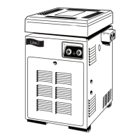
a
Remove drain plug from header and allow all
water to drain from heat exchanger.
b
Locate the threaded boss on the outlet port of
the header, and fi nd the dimple at the center.
Use the dimple to center the drill bit.
For header type A: Drill a 1/4 in (6.4 mm) diameter
hole through the boss.
For header type B: Drill a 3/8 in (9.5 mm) diameter
hole through the boss.
Take care not to damage the plastic threads.
TIP: Drilling a 1/8 in (3 mm) diameter hole fi rst will
help prevent thread damage.
d
Each male connection should be fi rst wrapped in
5-6 turns of PTFE (Tefl on) tape.
For header type A: Assemble the 3/8 in threaded
nipple, reducing bushing, elbow and pressure
relief valve. Make sure to get a sung fi t. Do not
overtighten.
Early models of JXi heaters utilized a different
header design that currently used in production, so
this heater may have one of two different header
design. See Figure 14 below to identify which header
design you have. The header type installed on your
JXi heater will determine which parts form this kit
are used. Please double check that you have all
necessary parts to complete the installation and that
all parts are damage free. If any parts are missing or
damaged please call 1-800-822-7933 for assistance.
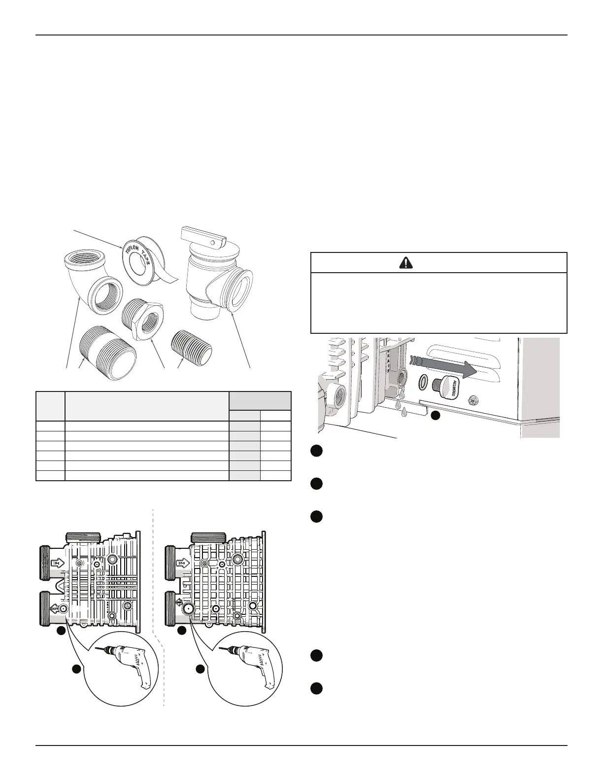
12345
6
ITEM Description
Header TypE
A B
1 Pressure Relief Valve 3/4 in X 3/4 in 50 PSI X X
2 Brass Nipple 3/8 in X
3 Reducer Bushing 3/8 in M to 3/4 in F NPT X
4 Brass Nipple 3/8 in X
5 Elbow 90° 3/4 in NPT Brass X X
6 PTFE (Tefl on
™
) Tape X X
Table 5. Pressure Relief Valve Kit Components/Usage
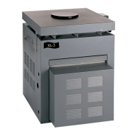
b
b
Drill Using
a 1/4 in Bit
Drill Using
a 3/8 in Bit
Heater Revision “K” and Earlier Heater Revision “L” and Later
Header Type “A” Header Type “B”
cc
TIP: Drilling a 1/8 in diameter hole first will help prevent thread damage.
Figure 14. Identifying Header Design