Page 3
Jandy
®
Pro Series, LXi Maintain Heat Relay
|
Installation Kit Instructions
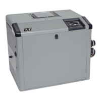
INTERMATIC
®
MODEL T104 MECHANICAL TIMER
(NOT PROVIDED IN THIS KIT)
INTERMATIC MODEL T104 (NOT PROVIDED WITH HEATER OR KIT) WIRE CONNECTIONS SHOWN AS AN EXAMPLE,
OTHER MODELS MAY HAVE DIFFERENT CONNECTIONS. CONSULT TIMER MANUFACTURER FOR PROPER CONNECTIONS.
FIELD INSTALLED COMPONENTS
OPTIONAL HEATER COMPONENTS
MAINTAIN HEAT (PUMP) RELAY
(SEE HEATER WIRING DIAGRAM)
240 VAC
PUMP
CLOCK
MOTOR
NOTE:
EQUIPMENT
GROUND
L2
L1
1
3
2
4
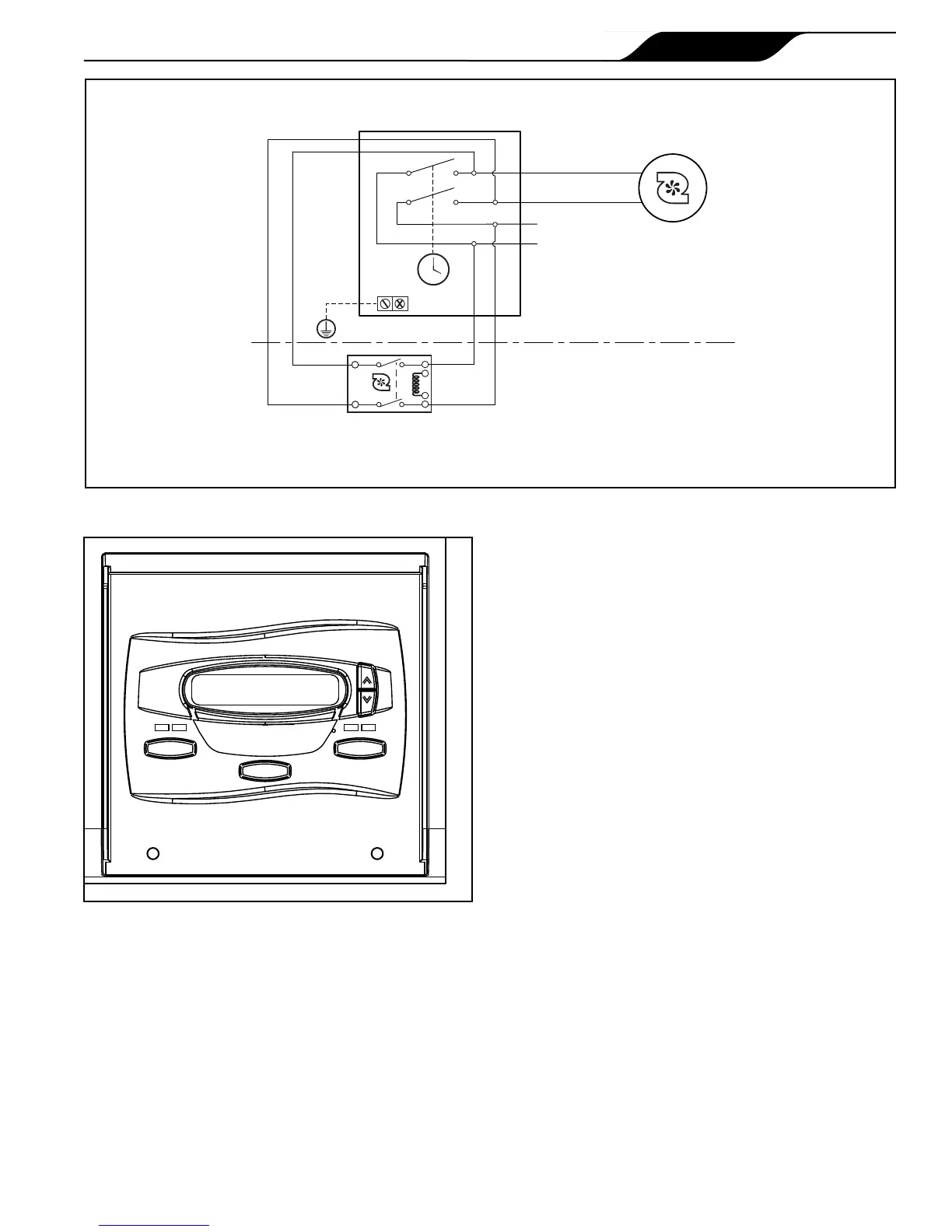
SPA
MENU
POOL
GAS HEATER IS OFF
PRESS POOL OR SPA
Figure 4. Main Control Panel
B. Congure the Universal Controller for
the Maintain Heat Feature
1. Maintain Temperature
a. Make sure the control is in the OFF mode. See
Figure 4.
b. To enter the Service Setup mode, press and hold
the
MENU, POOL and SPA buttons for ve (5)
seconds.
NOTE The display will revert back to OFF after one (1)
minute since the last key press.
c. When connected, this option allows the heater
to control the pump even if the time clock
has turned the pump off. To select Maintain
Temperature, use the
Up or Down button to
display MAINTAIN TEMP.
Press the MENU button. The DISABLE (default
mode) appears, use the Up or Down button to
scroll to ENABLE, press the MENU button to
select. Press POOL or SPA to exit the Service
Setup mode.
2. Maintain Temperature Delay
a. Make sure the control is in the OFF mode.
b. To enter the Service Setup mode, press and hold
the
MENU, POOL and SPA button for ve (5)
seconds.
NOTE The display will revert back to OFF after one (1)
minute since the last key press.
c. The maintain temperature delay is used when
MAINTAIN TEMP is connected. This feature
allows for a time delay before the pump is
turned on. To select Maintain Temperature
Delay, use the Up or Down button to scroll
through to display MAINTAIN TEMP DELAY.
Press the MENU button. The 01:00 HRS
(default time) appears, use the Up or Down
button to scroll to display the desired time delay,
press the MENU button to select. Press POOL
or SPA to exit the Service Setup mode.
Figure 3. Maintain Heat (Pump) Relay
 Loading...


