installation instructions
Model VC
page 6 of 12
JARVIS
6222009::.
PRODUCTS CORPORATION
33 ANDERSON ROAD, MIDDLETOWN, CONNECTICUT 06457-- 4926
UNITED STATES OF AMERICA E--MAIL. jarvis.products.corp@snet.net
TEL. 860--347--7271 FAX. 860--347--6978 WWW.jarvisproducts.com
®
15 inch
Approx.
3--6 inch
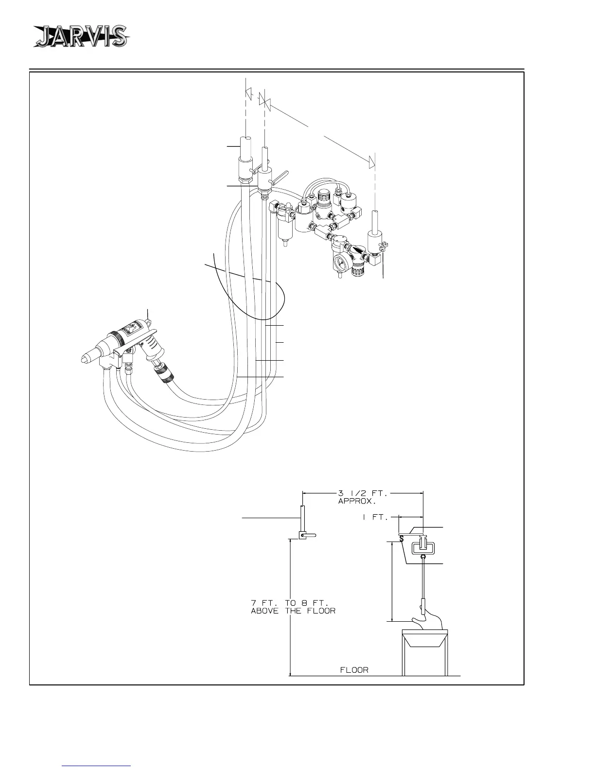
Water Tube (1323019)
Vacuum Hose (1323010)
Air Hose (1323011)
Model VC
Air Control Circuit
To Vacuum Tank:
1
1
/
2
inch Pipe min.
1
/
4
Turn Shutoff Valve
To Water Supply:
1
/
2
inch Pipe
1
/
4
Turn Shutoff Valve
Tie all tubes and
hoses together.
To compressed
air supply:
1
/
2
inch Pipe
Trigger Control Hose (1323015)
Figure C
To Balancer
The vacuum pipe,
water pipe, air pipe
should all end at the
same height from
the floor.
Trough
Weld “s” hook
to angle or pipe.
Hang tool ba-
lancer from “s”
hook.
Weld angle or
pipe to rail.
Figure D
The tool
should be
suspended
at this level.
 Loading...