installation instructions
and specifications
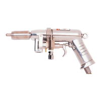
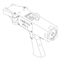
Model VC
page 7 of 12
JARVIS
6222009::.
PRODUCTS CORPORATION
33 ANDERSON ROAD, MIDDLETOWN, CONNECTICUT 06457-- 4926
UNITED STATES OF AMERICA E--MAIL. jarvis.products.corp@snet.net
TEL. 860--347--7271 FAX. 860--347--6978 WWW.jarvisproducts.com
®
SPECIFICATIONS
Model VC
Operating Pressure 30-60 psi 2.0-4.1 bar
Air Consumption 5.6-14 ft
3
/min 0.16--0.39 m
3
/min
Vacuum Requirements 15 in Hg 50.8 kPa
Air Flow(vacuum) 6--7 ft
3
/min 0.16--0.19 m
3/
min
Capacity Limited b y operator skill (avg. 3000 / hour)
Control Handle Single Trigger
Blade Dia. (range) 0.75--1.75 in 19--44 mm
Blade Length (range) 0.88--3.50 in 22--89 mm
Overall Length 11.0 in 267 mm
Weight 3.2 lbs 1.45 kg
INSTALLATION INSTRUCTIONS
1 Make a bracket to suspend the Model VC and ba-
lancer. Refer to Figure D, page 6.
2 Install a balancer (1350084) from the bracket. Refer
to Figures C and D, page 6.
3 Suspend the Model VC from a balancer (1350084).
Refer to Figures C and D, page 6.
4 Make the necessary vacuum connection. Refer to
Figures C and D, page 6.
5 Make the necessary water connection. Refer to Fig-
ures C and D, page 6.
6 Make the necessary air connection. Refer to Figures
C and D, page 6.
6.1 The air control circuit (3350006) must be in-
stalled in the air supply line.
6.1.1 The required compressed air supply is 14
ft
3
/min at 60 psi.
7 Model VC hook--up. Refer to Figure C, page 6. Re-
fer to pages 4 and 5 for all referenced items.
7.1 Vacuum:
7.1.1 Attach the 8 ft. vacuum hose (1323010) to
the vacuum supply.
7.1.2 Attach the 8 ft. vacuum hose (1323010) to
connector (item 5).
7.2 Water:
7.2.1 Attach the 8 ft. water tube (1323019) to the
water supply.
7.2.2 Attach the 8 ft. water tube (1323019) to con-
nector assembly (item 13).
7.3 Air:
7.3.1 Attach the air hose (1323011) to street el-
bow (item 56).
7.3.2 Attach the air hose (1323011) to quick con-
nect coupling (item 31).
7.3.3 Attach trigger control hose (1323015) to
tube connector (item 51).
7.3.4 Attach trigger control hose (1323015) to
tube connector (item 10).
 Loading...